USB-controlled RGB Led
Overview
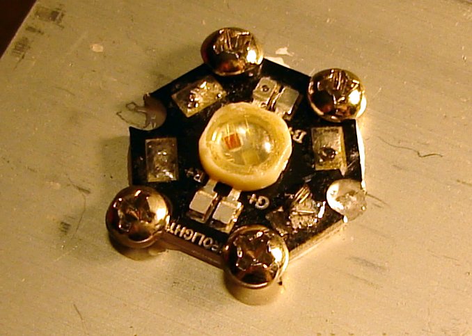
Prolight 3W RGB
My goal was to control the lamp from an USB port, in order to be able to change it's color according to different events or system statuses. For instance, flashes upon new email reception, controlling the intensity of a given color according to the system load average or according to audio output...
Prototype
Control PCB
News
- May 2011: Finally after 4 years, wrote the remaining parts, translated to english and published this project.
- February 2007: Most of this page written.
The LED

3 colors
Such a powerful LEDs produce a great light output, and produces a relatively high heat output as well. Cooling is therefore necessary to prevent self-destruction, and to keep the light output from dropping. (Output drops with rising temperature, see curves in the datasheet).
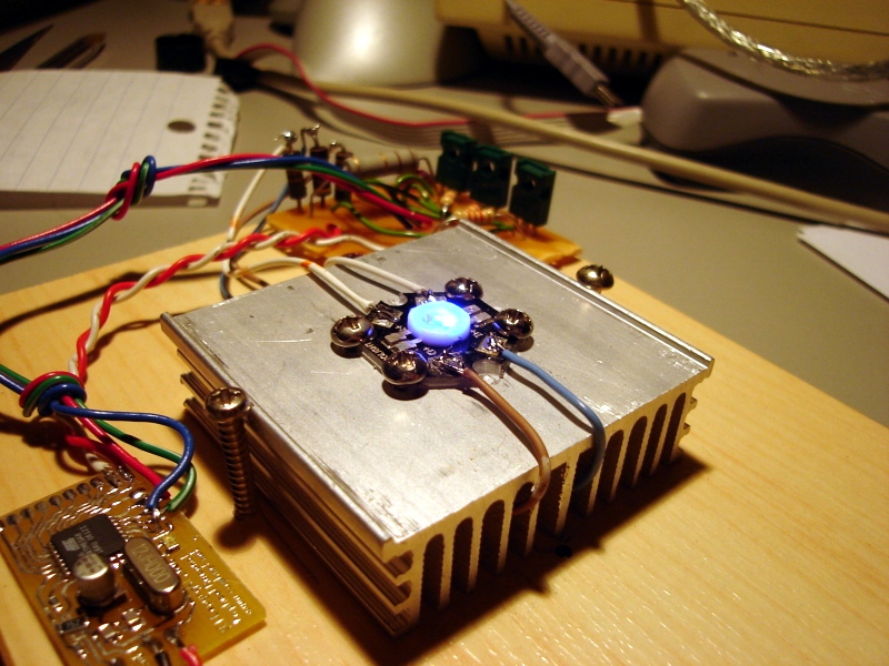
I used an old heat sink (Destined to socket 7 CPUs, e.g. Pentium 1) and thermal joint compound to help heat transfer from the LED to the heat-sink. I drilled holes in the heat sink and used sligtly bigger screws. Thanks to aluminium's malleability, I managed to install the screws without tapping the holes. Self tapping screws would probably have been a good choice here.
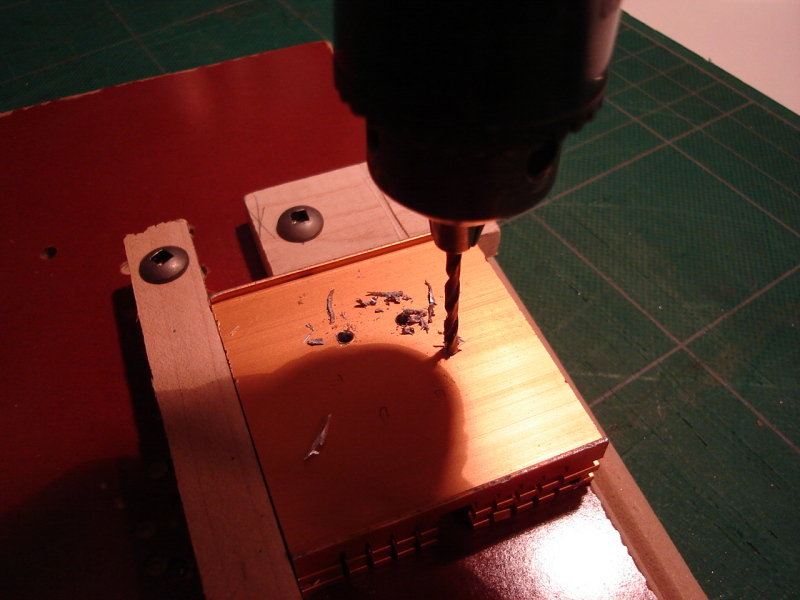
Perçage
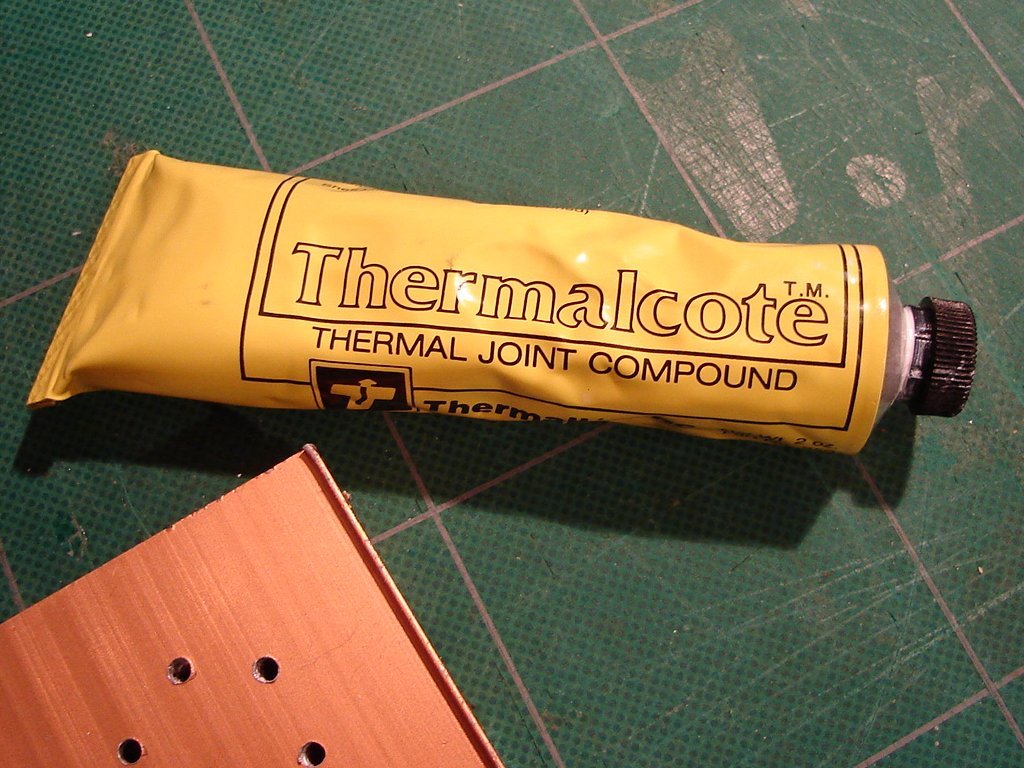
Pâte thermique? (Thermal joint compound)
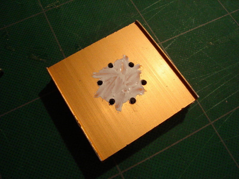
Pâte thermique appliquée
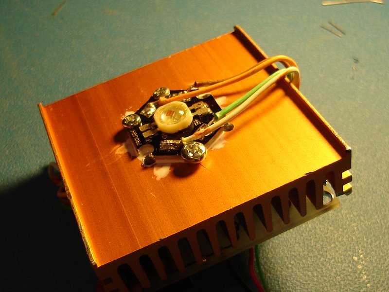
Led installé
Prototype
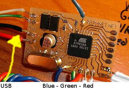
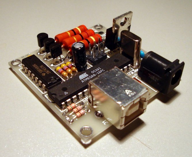
Wiring on multiuse-tiny1 circuit
This circuits has all the components necessary to use the Objective Development V-USB software-only USB,including the zener diodes which are required for maximum portablity. This picture shows where I soldered the USB wires and the 3 PWM outputs for the red, green and blue leds. The other wires are used to (re)program the AVR.
I was aiming at fully powered by USB solution, but the USB standard does not allow a device to draw more than 500 mA so I had to raise the resistor values for each channel. I targeted 150mA per channel, total 450mA. The remaining 50mA is more than enough for the other components in the circuit.
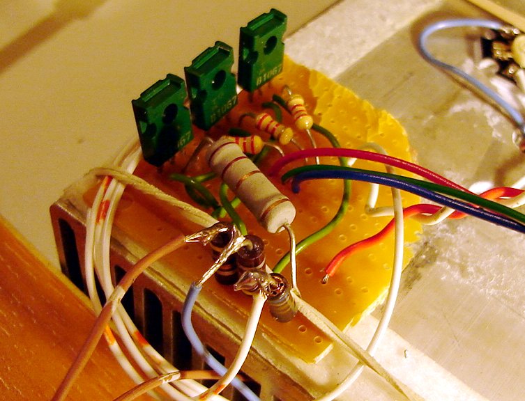
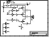
Darlignton transistors and resistors
Here's how the transistors are wired ot the Atmega8:
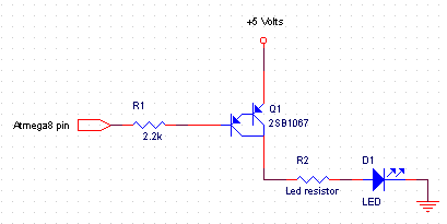 Circuit explaination:
When the atmega8 io pin is high (5 volts), the voltage on the transistor base equals
the emitter voltage so no current is flowing. If there's no current flowing between
the base and emitter, there won't be any between the emitter and collector. In other words,
the LED is off.
Circuit explaination:
When the atmega8 io pin is high (5 volts), the voltage on the transistor base equals
the emitter voltage so no current is flowing. If there's no current flowing between
the base and emitter, there won't be any between the emitter and collector. In other words,
the LED is off.But when the atmega8 io pin is low (0 volts), there is a voltage difference and therefore a current flowing from the Emitter to the base. The R1 resistor limits the current to a reasonable but sufficient level. This small current between the transistor emitter and base translates to a larger current flowing from the emitter to the collector, and then through the LED, which will turn on.
Now about selecting resistors for the LEDs. First, we need to know how many volts will be lost in the circuit. According to the datasheet, at a 150mA current, the red LED will have a 2v voltage drop, and the green and blue LEDs will exhibit a 3.3v drop. The transistor also incurs a voltage drop. For instance, the 2SB1067 transistor I used would have a 0.9v drop at 300mA when operating at 25°C. All of the above will also depend on temperature and vary between components...
| Calculating the ideal resistor value for a 5 volt supply and target current of 150mA. Transistor voltage drop (Vce)=0.9V. | |||
|---|---|---|---|
| Color | LED Voltage drop | Calculations | Resistance |
| Rede | 2.00 | (5V - 2V - 0.9V) / 0.150A | 14 ohms |
| Green | 3.30 | (5V - 3.3V - 0.9V) / 0.150A | 5.33 ohms |
| Blue | 3.30 | (5V - 3.3V - 0.9V) / 0.150A | 5.33 ohms |
Here are the real life results measured on the prorotype, with non-optimal resistor values (I used what I had on hand to get close enough). The voltage drop for the green and blue LEDs was lower than expected while the red LEDs is pretty close to theory. The USB supply voltage was only 4.86 volts. This may be losses from the USB cable. The voltage only drops this low when the LEDs are on... Also note the transistor voltage drop of only .7 volts instead of .9 volts.
| Real life LED voltage drops and currents | ||||
|---|---|---|---|---|
| Coor | LED Voltage | Transistor voltage | Voltage accross the resistor | Current |
| Red | 2.08V | 0.75V | 2.03V | 250mA |
| Green | 3.23V | 0.72V | 0.96V | 180mA |
| Blue | 3.12V | 0.74V | 1.06V | 190mA |
That said, I will now reveal the resistor values I used (NOT GOOD FOR USB, too low) for the prorotype:
Blue and Green: 4.7 ohms, Red: 7.9 ohms (6.8 ohms in series with 1.1 ohms)
| Ideal resistor values based on real life measure (transistor Vce=0.75v) | ||
|---|---|---|
| Color | Current | Resistor value |
| Red | 150 mA | (5V - 2.08V - 0.75V) / 0.150A = 14 ohms |
| Green | 150 mA | (5V - 3.23V - 0.75V) / 0.150A = 6.8 ohms |
| Blue | 150 mA | (5V - 3.12V - 0.75V) / 0.150A = 7.53 ohms |
Here's a few pictures of the working prototype:
Blue led only, at a very low intensity
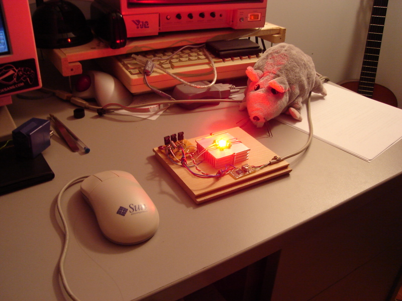
The red led at full power, in a well lit room
Version 1
Shorlty after completing the successful protype, I began working on an easily reproducible version. In other words, a PCB and a list of components that were easy to find at the time.I designed version 1 with the following changes, improvements and goals in mind:
- Add a separate power input to provide more power for the LEDs.
- Support an input voltage above 5 volt. Failure: The resistors heat too much. Would need higher wattage resistors or more efficient circuit.
- Use a single PCB for all components. No more wires and separate transistor circuit. (Ok, only wires to the LED)
- Use compoents easy to find in 2007 at my usual supplier, Digikey.
Bill of material:
| Ref | Description | Quantity | # Digikey |
|---|---|---|---|
| Q2,Q3,Q4 | MPSA63 Transistor | 3 | MPSA63-ND |
| U2 | open-collector output buffers | 1 | 296-14647-5-ND |
| J3 | Power connector | 1 | PJ-202AH |
| U1 | ATmega8-16PC MCU | 1 | ATMEGA8-16PC-ND |
| Y1 | 12 mhz crysta; | 1 | X983-ND |
| C2,C3 | 30pf capacitor | 2 | 490-3721-ND |
| C1 | 10uf capacitor | 1 | 493-1077-ND |
| J2 | Header 2x3 | 1 | WM7406-ND |
| D3,D6 | 2A 20V Diode | 2 | SR202-TPCT-ND |
| C5 | .1uf capacitor | 2 | BC1148CT-ND |
| C4 | 1uf capacitor | 1 | P993-ND |
| R1 | 1.5K resistor | 1 | P1.5KBACT-ND |
| R2,R3 | 68 ohms resistor | 2 | P68BACT-ND |
| R6,R8,R10 | 470 ohms resistor | 3 | P470BACT-ND |
| D1,D2 | Diode Zener 3.6 volts | 2 | 1N4729A-TPCT-ND |
That's not all!
The transistor is not the one that was used for the prototype so we need to recalculate the resistor values. According to the MPSA63 datasheet, the saturation voltage (Vce) would be 1.5v. But in practise, is appears to be only .75v.. Mais en pratique, le transistor ne semble pas se comporter ainsi. Le voltage Collecteur-Emetteur est de seulement 0.75 volts.
| Resistor values for 150mA and 300mA targets, with transistor Vce=0.75v. | |||
|---|---|---|---|
| Color | Target current | Resistance | Dissipation |
| Red | 150mA | (5V - 2.08V - .75V) / .150A = 14.5 ohms | (5V - 2.08V - 0.75V) * .150A = 0.33 Watts |
| 300mA | (5V - 2.08V - .75V) / .300A = 7.2 ohms | (5V - 2.08V - 0.75V) * .300A = 0.7 Watts | |
| Green | 150mA | (5V - 3.23V - .75V) / .150A = 6.8 ohms | (5V - 3.23V - 0.75V) * .150A = 0.15 Watts |
| 300mA | (5V - 3.23V - .75V) / .300A = 3.4 ohms | (5V - 3.23V - 0.75V) * .300A = 0.30 Watts | |
| Blue | 150mA | (5V - 3.12V - .75V) / .150A = 7.5 ohms | (5V - 3.12V - 0.75V) * .150A = 0.17 Watts |
| 300mA | (5V - 3.12V - .75V) / .300A = 3.8 ohms | (5V - 3.12V - 0.75V) * .300A = 0.34 Watts | |
Now that we know the resistor value and wattage, we need to buy these. It is important to use resistors with approximately twice the calculated wattage.
If you will be powering the circuit from USB (i.e. 150mA per color) and you cannot locate a resistor with the exact value, you should use a higher value (for a current slightly lower than 150mA). But if you will be powering the circuit from another source (with 300mA target), you may use lower resistor values (for higher current) since the real limit is 350mA, not 300mA.
| Ref | Description | # Digikey | What for |
|---|---|---|---|
| R7 | 15 ohms, 0.6W resistor | PPC15.0ZCT-ND | Red 150mA |
| R7 | 7.5 ohms, 2W resistor | PPC7.5W-2CT-ND | Red 300mA |
| R7 | Pair of 3.6 ohms, 2W resistors | BC3.6W-2CT-ND | Slightly more accurate for RED at 300mA |
| R9 | 6.8 ohms, 1W resistor | PPC6.8W-1CT-ND | Vert 150mA |
| R9 | 3.3 ohms, 1W resistor | PPC3.3W-1CT-ND | Vert 300mA |
| R11 | 7.5 ohms, 1W resistor | BC7.5W-1CT-ND | Bleu 150mA |
| R11 | 3.6 ohms, 2W resistor | BC3.6W-2CT-ND | Bleu 300mA |
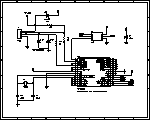
PCB for version 1
Here's a composite view of the PCB: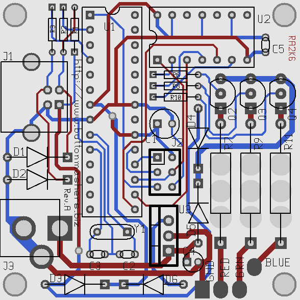
I used an open-source software named PCB to design this circuit. Here's the source file for the circuit in this software's native format: prod1.pcb
If you cannot use the original file, here's the PCB in gerber format:
rgbledsA.zip
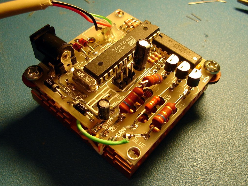
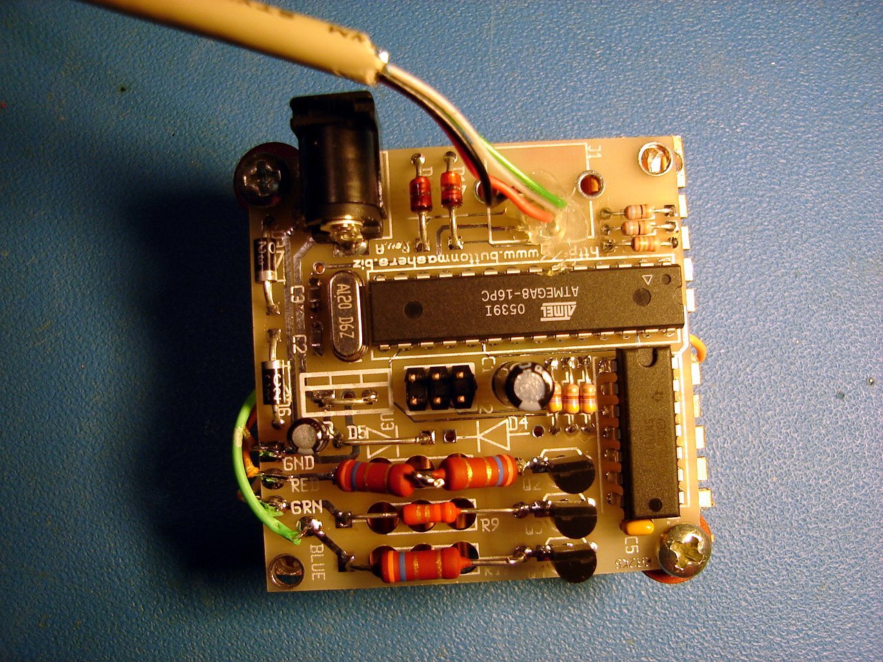
The pictures below show the PCB assembled for an external power supply where the LED will operate at approximately 300mA per color component. The MCU is powered from USB or from the external supply.

Theory
The intensity of the light output by the LED is controlled by changing the duration of a period where the LED is on versus the duration of the period where the LED is off. The operating frequency was chosen to be high enough for the human eye to perceive a continuous output whose intensity will depend on the ON-OFF ratio.This technique is very common and is known as pulse-width modulation (PWM). Here's a wikipedia page on the subject:
http://en.wikipedia.org/wiki/Pulse-width_modulation
MCU source code
The MCU source code is here: rgbleds-1.0.tar.gz.On a linux system on which the AVR development tools have been installed (avr-gcc, avr-libc, etc), you only need to type 'make' in the directory where you'll have extracted the archive. Have a look to the 'fuse' and 'flash' makefile targets for programming the AVR. If needed, have a look to my How to program an AVR page for details on how this is done.
The USB software-only implementation is an old version of V-USB par Objective development. (I'm sorry, but for now I don't have the time to update this project to a newer version of V-USB).
Host PC software
Included with the source archive above, these are simple tools that can be used as examples and should be easily adapter to your needs. They all use libusb and were tested under Linux only.| Location | Description |
|---|---|
| cmdline/ | Simple command line tool. |
| misc_examples/ | LED controlled by system load and strobe demo. |
| qt/ | Simple GUI using sliders to control the LEDs based on the QT library. |
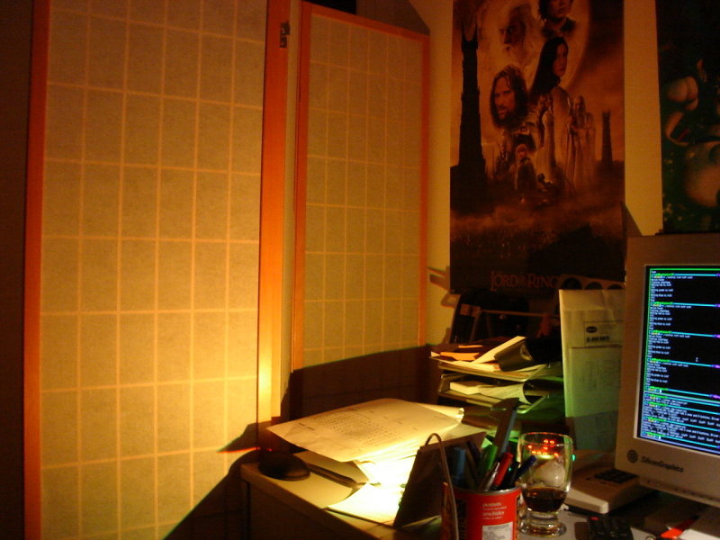
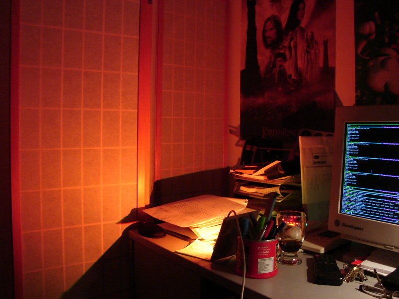
Pictures of the circuit, in-use
Démonstration de l'éclairage. Il y avait aussi une petite lampe de 20Watts et un écran d'ordinateur dans la pièce...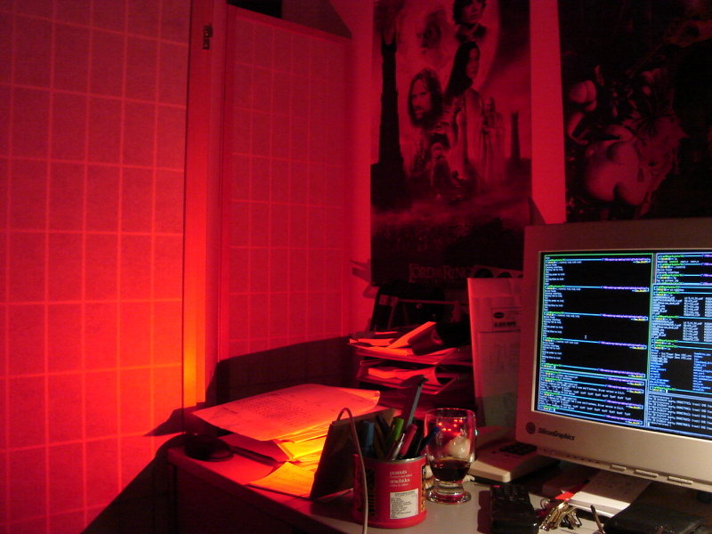
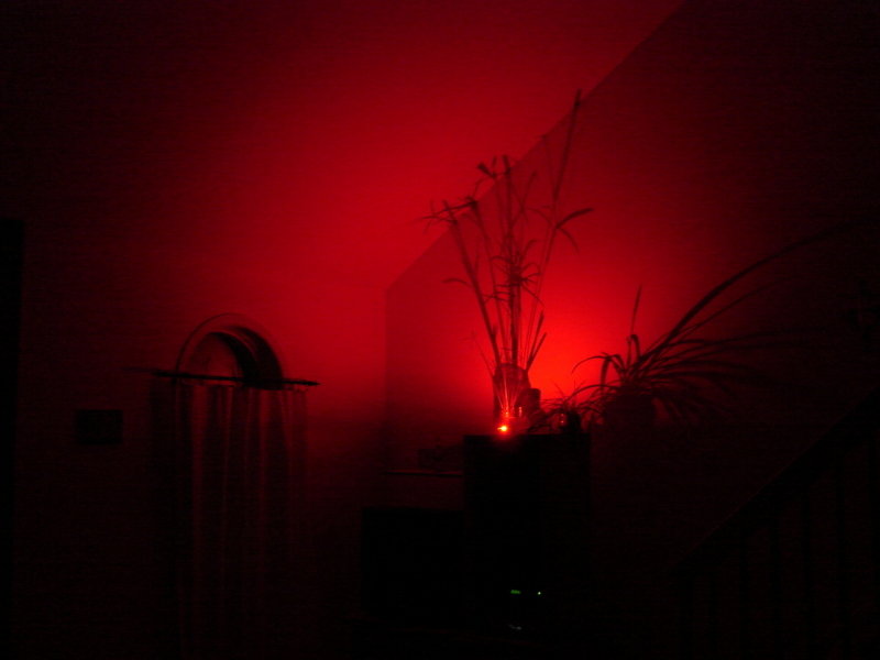
An area in my LAB lit in red...
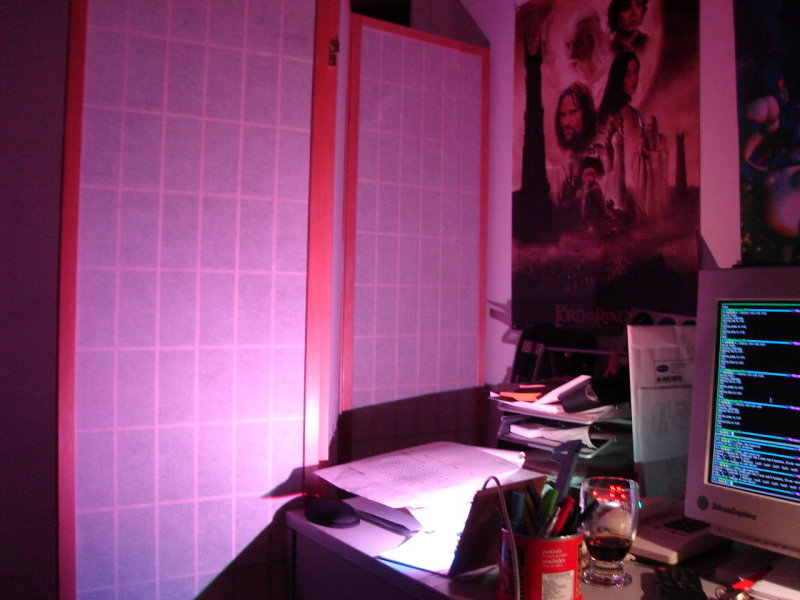
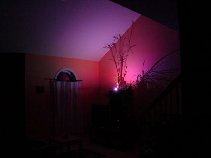
and in purple...
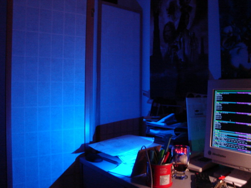
then in blue...
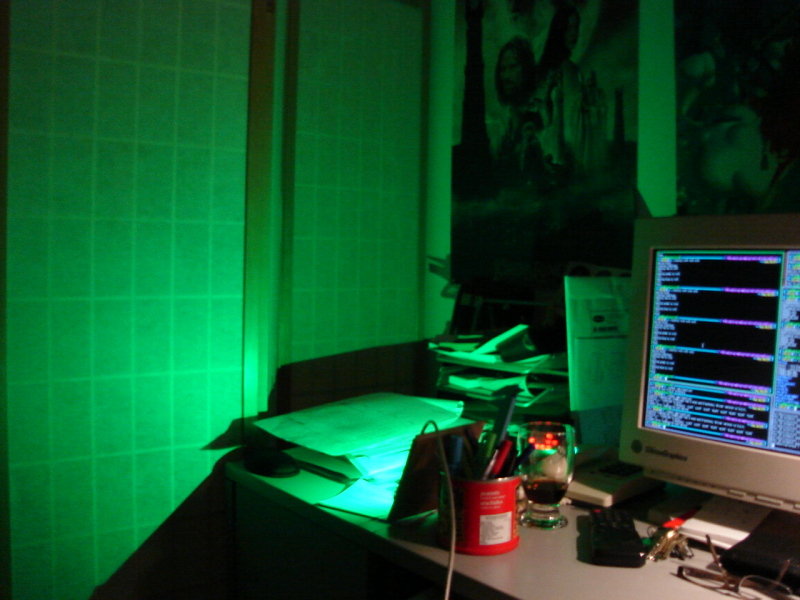
now in green...
in yellow...
and finally orange.
If the light goes through a small paper cylinder, we can project a circle like this. We can then witness an interesting phenomenon due to the fact that the red, green and blue light source come from different spots inside the LED... (The Red+Green+Blue picture is the most interesting)
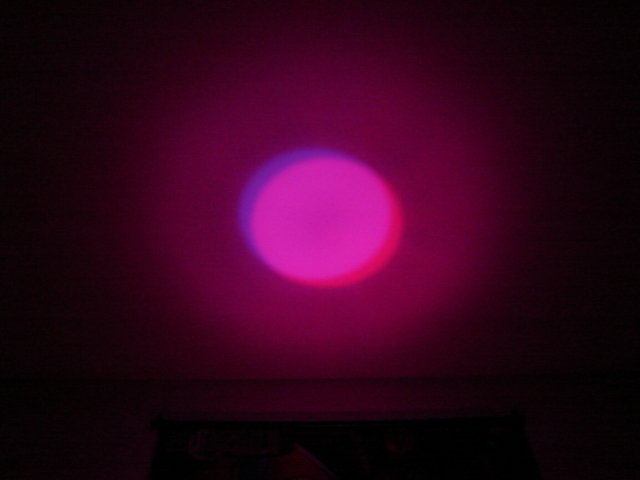
Red + Blue

Green + Blue
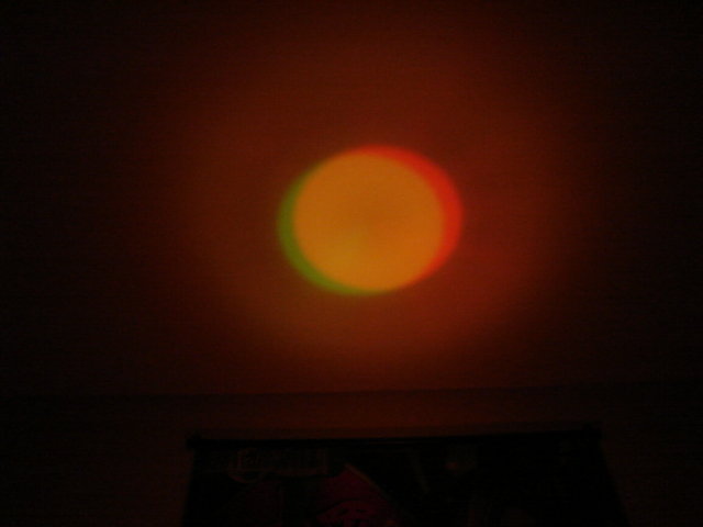
Red + Green

Red + Green + Blue
Pictures from the living room with no light source but the LED:
User pictures
If you build this project, I would appreciate seeing your pictures and publishing them in this section if you allow it.Disclaimer
I cannot be held responsible for any damages that could occur to you or your equipment while following the procedures present on this page. Also, I GIVE ABSOLUTELY NO WARRANTY on the correctness and usability of the informations on this page. Please note, however, that the procedures above have worked in my case without any damages or problems.Now you cannot say that I did not warn you :)