N64/Gamecube controller to USB adapter
Project Overview
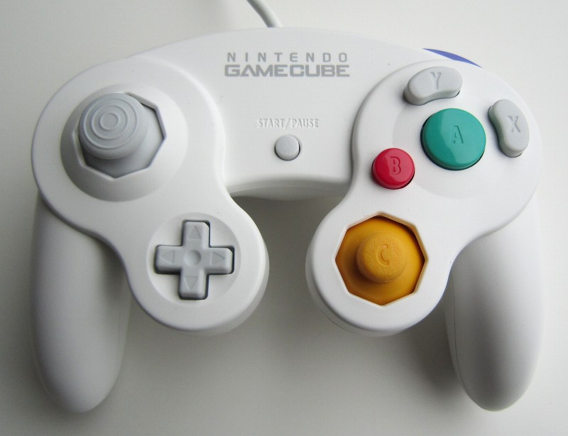
 Nintendo 64 and Gamecube controllers are excellent controllers which are quite appropriate
for many PC games, and of course are perfect for emulators!. The microcontroller
firmware in this projet implements a standard HID joystick which means that no
special device driver is required. It works perfectly well under Linux and Windows.
Nintendo 64 and Gamecube controllers are excellent controllers which are quite appropriate
for many PC games, and of course are perfect for emulators!. The microcontroller
firmware in this projet implements a standard HID joystick which means that no
special device driver is required. It works perfectly well under Linux and Windows.
Features:
|
Why?
One of my friends wanted to play Nintendo 64 games on his PC using an original controller... so I developped an adapter for doing this. But since Gamecube controllers use a very similar protocol, it was easy to support Gamecube controllers too.
Gamecube and Nintendo 64 controllers both work at 3.3 volts. But on the USB bus, only 5 volts are available. For this reason, a voltage regulator is required. Apart from the different firmware, this is the only difference (and additional complexity) this project has with my Nes/Snes controller to USB project.
 Ready to use adapters available
Pictures
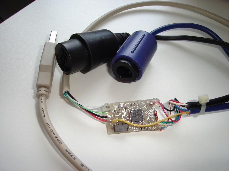
Adapter example
N64 or Gamecube to USB with regulator on-board: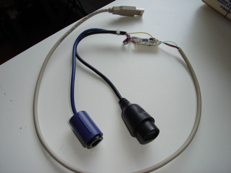

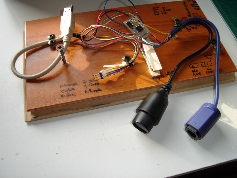
Controller conversion
An example of permanently converting a N64 controller to USB. There is not much space inside, but by removing a small amount of plastic, the circuit fits well in the controller's middle "finger". The layout of the wires must be carefully planned in order not to interfere with the cover. I used hot glue to hold them in place.


Historic/Development pictures
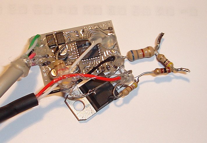
Pictures of the printed circuit board with an lm1117 adjustable voltage regulator:
Top

Bottom

small fix
Pictures taken during development with the new PCB:


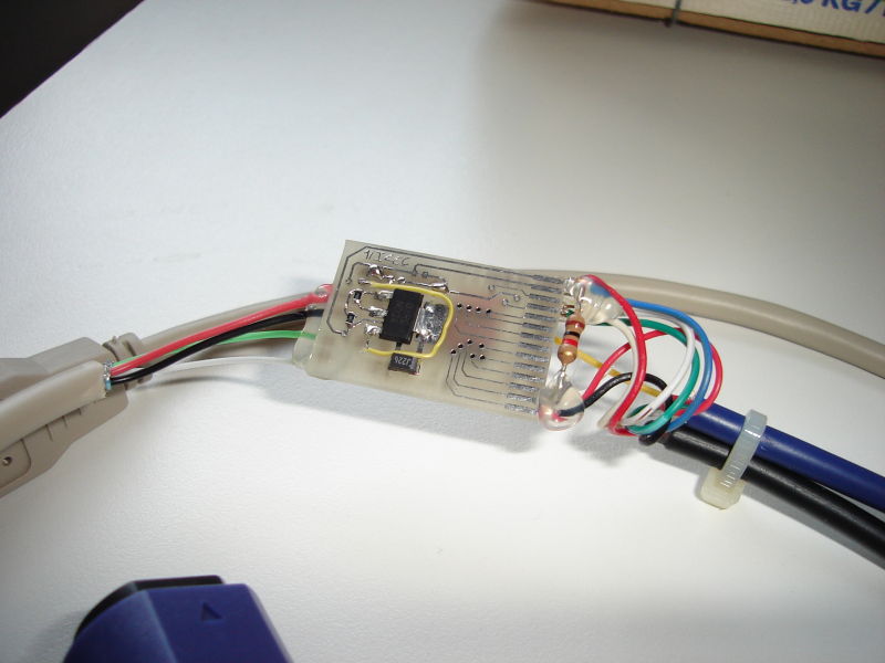
Pictures of the N64 to USB prototype. I used an lm317 adjustable voltage regulator:

The N64 Hori-mini and white Gamecube controller with extra long cable work!

The Gamecube keyboard is supported since version 2.9.

Contributions
Here are some pictures from Declan Williams (16 years old!):


Sean Green built and used my circuit in a few projects:
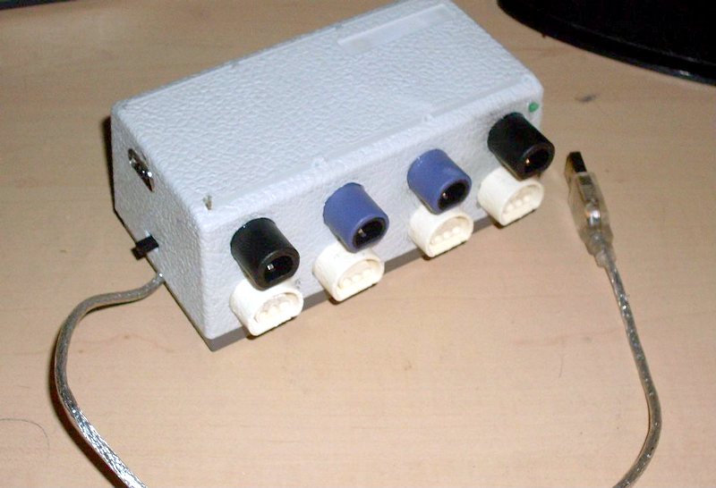
The Bliss 4-pack

The Bliss Worm


Note: The bliss 4pack displayed here is NOT a 4 player version of the project. It is only an USB HUB with 4 built-in GC/N64 to USB converters.
2013-02-14: Ludivine built a N64 adapter based on this project. The voltage regulator is on the back side of the PCB.

July 19, 2014 (Saturday)
TALENTO from Bulgaria sent me pictures of the GC/N64 to USB adapter he built on universal board.


October 5, 2014 (Sunday)
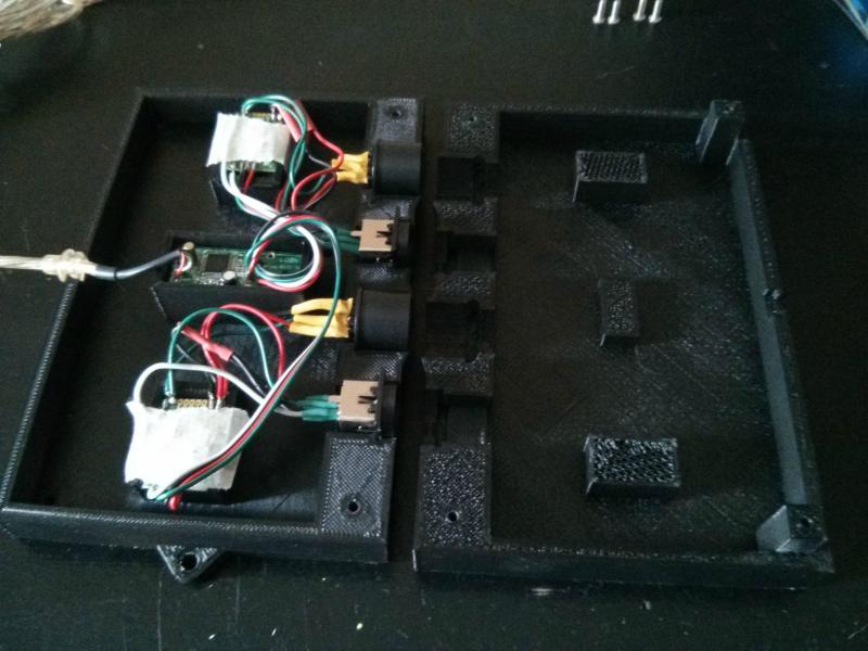
Browner87 used a 3D printer to build an enclosure housing a pair of GC/N64 to USB circuits, four controller connectors and an USB Hub. Additional comments and pictures available on imgur.


October 11, 2014 (Saturday)
Jonathan sent me the following pictures of the Gamecube to USB adapter he built. He used an Atmega8L-8PU which is therefore overclocked. But it seems to work fine for him.


March 10, 2015 (Tuesday)
Rickey sent me a picture of the adapter he build on a breadboard. He used an ATMega328P programmed with the Atmega168 firmware and fuses and everything works!

March 25, 2015 (Wednesday)
Ashley form Queensland, Australia, is helping his little brother Shaun (who's 14) with a few projects to get him interested in something other than just playing games. Together they built the SNES/NES to USB and Gamecube/N64 to USB circuit on a single breadboard. Components are on their way for the final version.


Schematics
Here are the schematics: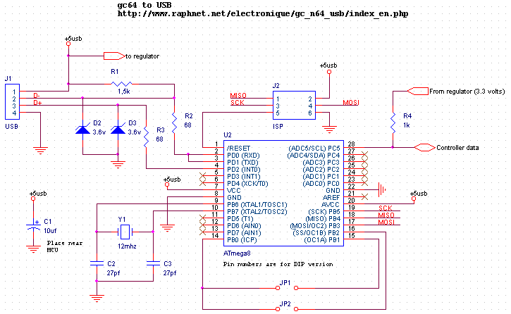

Comments: Some webpages mention that the Gamecube controllers work at 3.43 volts, some other pages says it's any voltage between 3.3 and 3.8! volts... I read an old message in the comp.emulators.game-consoles news group where the author said that the Nintendo 64 supplies 5 volts to the controllers (Wrong!). I measured 3.36 volts on my N64 so personally, I choose to supply 3.3 volts to my Gamecube and N64 controllers.
In order to obtain 3.3 volts, you can use a fixed voltage regulator such as the 78M33C or an adjustable voltage regulator such as the lm317 or lm1117 (exemple). If you use an lm317 variable voltage regulator, here's a simple tool which can help you find a good value for R1. Any voltage between 3.26 and 3.40 volts should do the job.
Wavebird color code (for reference only)
I have been informed that the color of the wires running from the gamecube connector to the PCB inside the receiver seem to be constant:
- +3.3v: Rouge
- Data: Green
- GND: Brown (Pin)
- GND: Violet (Shield)
Printed Circuit Board
Top
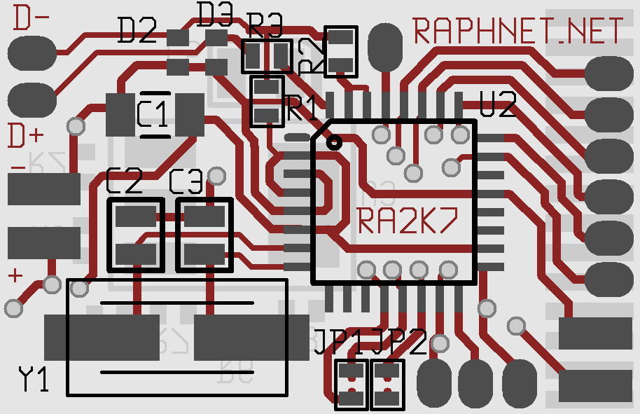

Bottom

Here is a wiring diagram for the board:

And finally, here are the gerber files which you can use produce this PCB:
multiuse.zip
Due to the fact that this board is two-sided and has numerous vias, building it at home may be a little harder than the ususal. If you want, you can get professional PCBs from my online store. The PCBs from my store, however, are a little older than the one above. I've had a huge quantity produced with a small mistake: The 5 volts supply from the USB bus does not reach the regulator!
In order to correct this, a small wire has to be installed on the bottom side:
Correction
Firmware
| Version v2.9.2 December 9, 2015 (Wednesday) |
|---|
|
| File(s): gc_n64_usb-2.9.2.tar.gz (474.4 KB) gc_n64_usb-m8-2.9.2.hex (19 KB) gc_n64_usb-m168-2.9.2.hex (19.7 KB) |
Show previous releases...
| Version v2.9.1 April 17, 2014 (Thursday) |
|---|
Minor fixes and improvements:
|
| File(s): gc_n64_usb-2.9.1.tar.gz (473.6 KB) gc_n64_usb-m8-2.9.1.hex (19 KB) gc_n64_usb-m168-2.9.1.hex (19.7 KB) |
| Version v2.9 November 24, 2013 (Sunday) |
|---|
Keyboard support and maintenance:
|
| File(s): gc_n64_usb-2.9.tar.gz (473.4 KB) gc_n64_usb-m8-2.9.hex (18.9 KB) gc_n64_usb-m168-2.9.hex (19.6 KB) |
| Version v2.3 June 24, 2013 (Monday) |
|---|
|
| File(s): gc_n64_usb-2.3.tar.gz (481.2 KB) gc_n64_usb-m8-2.3.hex (18.1 KB) gc_n64_usb-m168-2.3.hex (18.6 KB) |
| Version v2.2 February 12, 2013 (Tuesday) |
|---|
|
| File(s): gc_n64_usb-2.2.tar.gz (139.7 KB) gc_n64_usb-2.2.hex (18.7 KB) |
| Version v2.1 November 13, 2011 (Sunday) |
|---|
|
| File(s): gc_n64_usb-2.1.tar.gz (114.9 KB) gc_n64_usb-2.1.hex (18.6 KB) |
| Version v2.0 November 1, 2011 (Tuesday) |
|---|
|
| File(s): gc_n64_usb-2.0.tar.gz (116 KB) gc_n64_usb-2.0.hex (18.5 KB) |
| Version v1.4 June 11, 2011 (Saturday) |
|---|
|
| File(s): gc_n64_usb-1.4.tar.gz (97.8 KB) gc_n64_usb-1.4.hex (12 KB) |
| Version v1.3 May 1, 2011 (Sunday) |
|---|
|
| File(s): gc_n64_usb-1.3.tar.gz (97.3 KB) gc_n64_usb-1.3.hex (12 KB) |
 This project is also available on GitHub!
To request features, report issues or contribute, you may send me an email or use the GitHub repository:
https://github.com/raphnet/gc_n64_usb
The source code is available under the GPLv2 license. See License.txt for more information. The project compiles with avr-gcc.
Using the .hex files
Hexfiles in the gc_n64_usb-m8-x.x.hex format are for Atmega8, files in the gc_n64_usb-m168-x.x.hex format are for Atmega168. (Note: I'm told that the mega168 firmware and fuse vales also work for Atmega328p)
The fuses settings for this projet are:
- For Atmega8: high_byte=0xc9 low_byte=0x9f.
- For Atmega168: HFUSE = 0xD5, LFUSE = 0xD7, EFUSE = 0x01.
Hori-mini support
Since firmware version 1.3, all Hori-mini N64 pads are expected to work correctly thanks to a new algorithm which is tolerant to timing. A technical explaination of the issue and solution is given below.Hori-mini N64 pads are known to misbehave with many adaptors. After testing a donated Hori-mini N64 pad with one of my adapters, they seemed to work properly... Until someone reported problems. When moving the axis, there would be sudden jumps to other positions, hindering gameplay. I tried my Hori controller with a few of my adapters and on a few computers. I eventually managed to find a unit which did not work well with my controller and began looking for the cause.
I noticed something unusual as soon as I looked at the communication between the Hori and my adapter. The Hori communication timing was very different from what I expected. The image below shows the low/high ratios for each bit being very different between the poll (from the adapter) and the answer (from the controller). The HORI controller replies at 66% the speed of a 'normal' N64 controller:
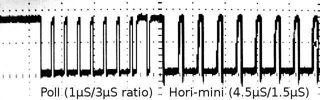


As you may already know, the bits are encoded as follows. Normally (at least with Nintendo's hardware), the timing is 3μs low/1μS high or 1μS low/3μS high for transmitting a 0 or 1 respectively. (See references for more information).

My original code simply waits for the initial falling edge and takes a
sample 2μS later. Under ideal conditions, the sample value (1 or 0) is
representative of the bit being sent. The 2μS delay means the sample
is taked perfectly in the center of the bit. This is nice but only works
if the controller uses the normal 1μS/3μS timing (or something close enough).
As we can see on the right, the sample position when receiving bits from a Hori-mini PAD is near the rising edge. And it works. But this is bad because in this situation, a small timing difference may cause malfunction ; there are not enough tolerances. And real life has proven this to be a problem.
As we can see on the right, the sample position when receiving bits from a Hori-mini PAD is near the rising edge. And it works. But this is bad because in this situation, a small timing difference may cause malfunction ; there are not enough tolerances. And real life has proven this to be a problem.
Normal timing Good: Sample centered |
Hori timing Bad: Sample near rising edge |
Why sampling near the rising edge is a problem:
- The sampling cannot be done exactly at 2μS. There is some jitter introduced by the polling loop used to detect the falling edge. In other words, some samples will be taken even closer to the rising edge, or during the rising edge.
- The Hori-mini PAD internal oscillator frequency may vary between units and with temperature. In other words, some controllers may send bits at a slightly slower rate (does not help) or faster (helps).
- The relatively slow-rising of the data line may also hinder reliability. At what point exactly will the MCU see a logic 1? This is in the MCU specs, but it may change slighly from unit to unit or with newer version of the chip (e.g. Atmega8a) And if an extension cable increases capacitance, the situation will be worst.
I concluded that I needed a better reception algorithm. Instead of sampling a little later or writing a new version that would measure the timing and adjust the sample position accordingly, I came up with something much better which will tolerate faster and much slower timings within a good margin:
- Measure the time until rising edge (low level duration)
- Measure the time until falling edge (high level duration)
- Compare time spent low vs. high, if more time was spent low, we got a 0. Otherwise, we got a 1.
- Repeat
USB Sync.
Since release 1.4, controller polling is synchronized with USB polls. The helps maintain accurate timing during communication with the controllers. It is hoped this will increase the (already quite good) compatibility and reliability of the circuit. Technocal explaination follows.
Transmission interrupted
When an USB interrupt occurs at the wrong moment, the gamecube/n64 protocol frame is potentially corrupted and if it is, it should be discarded. When trasmitting, we rely on the game controller to detect the error and drop the frame. Then we simply timeout waiting for the answer. If instead the interrupt occrurs during reception, we will miss some transitions and won't receive the number of bits we expected.
Despite of the above theory, it would seem that occasionally (once in several minutes) some errors are not detected. A few users had reported that from time to time buttons seem to be reported active for a brief moment (even though hey were not pressed) so I decided to eliminate this risk by preventing these interrupts from occuring at the wrong time. And indeed, with the new white Gamecube controllers, the only controller I could confirm the problem with, the problem appears to be gone.
Disabling interrupts during the timing sensitive communication is not possible due to the software USB implementation that does not allow us to disable them for long enough a time to be useful. On the other hand, we have approximately 900μS between interrupts which leaves us enough of time to communicate with the controller without being disturbed. We just need to synchronize with the USB interrupts and poll the controller when USB is idle.
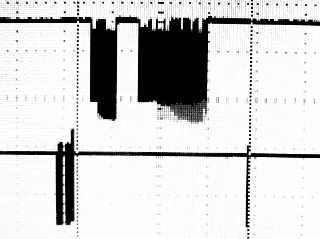
I thought of a very simple software solution. The logic which controls the controller polling rate stays the same. But just before the actual communication, the MCU is put in a sleep mode (IDLE mode). In this mode, normal execution stops until an interrupt occurs. When the execution resumes, we know an interrupt has occured and has been serviced so we can just continue and poll the controller. A small delay before polling helps us for cases where we receive a few interrupts in a burst.
With this solution implemented, the controller polling is always well placed inside the 900μS slot available between USB interrupts, as can be seen in the following screenshot:
GC/N64 and USB
L/R sliders calibration fixer

Uncorrected L/R sliders

Corrected L/R sliders
The following tool must be run after performing calibration (standard windows tools) . When it is run, it looks for raphnet GC/N64 to usb adapters and alters the calibration data the system keeps for each unit found. All axis are left as calibrated, except the L and R sliders which are recentered.
The tool can be downloaded right here:
gc_calfix_ng_v1.3.zip Supports all firmware versions.
A successfull operation will output something like this:

Previous versions:
gc_calfix_ng_v1.2.zip Supports up to firmware version 2.3.
Keyboard support
Since firmware version 2.9, the Gamecube keyboard is supported and can be used under Windows and Linux. Note that I only tested ASCII model ASC-1901P0. This keyboard has a dual-connector cable. The gray connector is for the keyboard function and the purple one for the Joystick function. To use both functionalities simultaneously with a PC, two adapters are required.Here are a few pictures of the keyboard:
General view

Keys (right part)
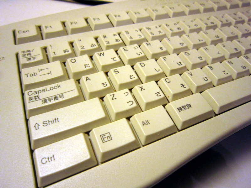
Keys (left part)

Interior

Interior
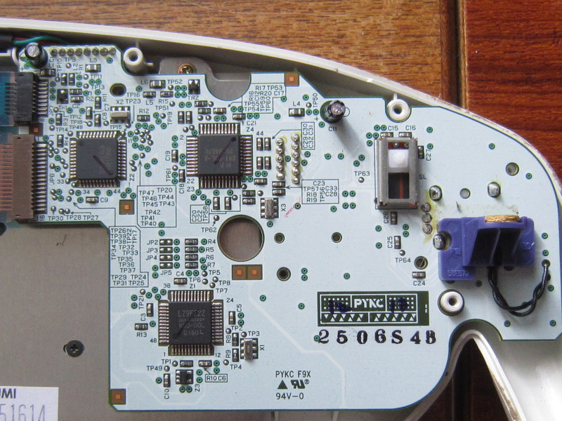
Interior
Development log and technical details
November 23, 2013The first thing I did was looking at what would be the answer to command 0x00 (GET ID). The adapter already uses this to detect the type of controller (N64 vs. GC) currently connected, so detecting the keyboard here was logical. I decoded the answer manually with a scope (much easier than for the Dreamcast controller communication protocol I was looking at recently...)
0000 1000 0010 0000 0000 0000 : 0x082000
Note: Only the first 16 bits are used for ID. So the keyboard ID is in fact 0x0820.
Shortly after, I looked at a good gamecube documentation[1] and confirmed I was getting the correct ID code, everything fine. I then continued experimenting and tried polling the keyboard using the command normally used to read the state of a controller (0x400300) but the keyboard did not answer. Not the right command. Back to the documentation, I learned comand 0x540000 should be used. Then of course, it worked.
The keyboard returns 64 bits (8 bytes):
| First 32-bit word | Second word: |
|---|---|
| Bit 31: Errstat | Bits 31-24: Keycode (1) |
| Bit 30: Errlatch | |
| Bits 29-28: ? | |
| Bits 27-24: Looks like a 4-bit counter. Purpose unknown. | |
| Bits 23-0: ? | Bits 23-16: Keycode (2) |
| Bits 15-8: Keycode (3) | |
| Bits 7: ? | |
| Bits 6-4: Maybe a checksum. Depends on the depressed button combinations. | |
| Bits 3-0: Looks like a 4-bit counter. Purpose unknown. |
This keyboard suports up to 3 simultaneous keypresses so I built the HID report descriptor accordingly. Usually, "special" keys such as CTRL, SHIFT and ALT are transmitted using dedicated bits in the report, but since the Gamecube keyboard does not have this concept and simply reports those keys like others (using full 8-bit keycodes), I do the same.
Unlike Dreamcast keyboards, this Gamecube keyboard does not use the keycodes from the USB HID Usage Tables document. (section 10 : Keyboard/Keypad page [0x07])
So I created a translation table. As this is a Japanese style keyboard, there are a few unusual keys and many won't produce the labelled characters unless the PC is configured to use a Japanese Keyboard.
| Gamecube Name(s) | Gamecube KeyCode(s) | HID Name(s) | HID KeyCode(s) | Comments |
|---|---|---|---|---|
| A - Z | 0x10 - 0x29 | A - Z | 0x04 - 0x1D | |
| 1 - 9 | 0x2A - 0x32 | 1 - 9 | 0x1E - 0x26 | |
| 0 | 0x33 | 0 | 0x27 | |
| ESC | 0x4C | ESC | 0x29 | |
| BACKSPACE | 0x50 | BACKSPACE | 0x2A | |
| TAB | TAB | 0x2B | ||
| SPACE | SPACE | 0x2C | ||
| _= | 0x34 | -_ | 0x2D | First key right of 0 |
| ^~ | 0x35 | =+ | 0x2E | Second key right of 0 |
| @` | 0x37 | [{ | 0x2f | First key right of P |
| [{ | 0x38 | ]} | 0x30 | Second key right of P |
| ]} | 0x3B | Non-US # and ~ | 0x32 | Third key right of L |
| ;+ | 0x39 | ;: | 0x33 | First key right of L |
| :* | 0x3A | '" | 0x34 | Second key right of L |
| 半角・全角 | 0x3F | `~ | 0x35 | |
| ,< | 0x3C | ,< | 0x36 | |
| .> | 0x3D | ,> | 0x37 | |
| /? | 0x3E | /? | 0x38 | |
| Caps lock・英数 | 0x53 | Caps lock | 0x39 | |
| F1 - F12 | 0x40 - 0x4B | F1 - F12 | 0x3A - 0x46 | |
| Scroll lock | 0x0A | Scroll lock | 0x47 | Accessible via FN |
| Insert | 0x4d | Insert | 0x49 | |
| Home | 0x06 | Home | 0x4A | Accessible via FN |
| PgUp | 0x08 | PgUp | 0x4B | Accessible via FN |
| Delete | 0x4E | Delete | 0x4C | |
| End | 0x07 | End | 0x4D | Accessible via FN |
| PgDn | 0x09 | PgDn | 0x4E | Accessible via FN |
| Right(→) | 0x5F | RightArrow | 0x4F | |
| Left(←) | 0x5C | LeftArrow | 0x50 | |
| Down(↓) | 0x5D | DownArrow | 0x51 | |
| Up(↑) | 0x5E | UpArrow | 0x52 | |
| Enter | 0x61 | Enter | 0x58 | |
| \_ | 0x3F | International 1 | 0x87 | Extra key after /? [HID usage tables Footnote 15-20] |
| カタカナ・ひらがな | 0x5B | International 2 | 0x88 | |
| ¥| | 0x36 | International 3 | 0x89 | Extra key before "back-space" |
| 全候補・変換(次候補) | 0x5A | International 4 | 0x8A | |
| 無変換 | 0x58 | International 5 | 0x8B | |
| CTRL (left) | 0x56 | Left control | 0xE0 | |
| SHIFT (left) | 0x54 | Left shift | 0xE1 | |
| SHIFT (right) | 0x55 | Right shift | 0xE5 | |
| ALT (left) | 0x57 | Right alt | 0xE6 | Actually a LEFT-ALT key on the keyboard, but RIGHT-ALT is required to access alternate key functions 漢字、漢字番号、全候補 and ローマ字. |
References:
[1] Joy-Bus Devices, section 9.1, ID and Device List
[2] Joy-Bus Devices, secion 9.3.2, Scancodes
DK Bongos support
 The DK Bongos act like a standard controller so the adapter supports them without complications.
| Bongo elements | Controller equivalent |
|---|---|
| Left pad (center) | Y |
| Left pad (front) | B |
| Right pad (centre) | X |
| Right pad (front) | A |
| Start button | Start |
| Microphone | R, varies with sound intensity. |
References
Technical informations concerning Nintendo 64 controllers:http://www.mixdown.ca/n64dev/
Technical information concerning the Gamecube controllers:
http://www.int03.co.uk/crema/hardware/gamecube/gc-control.htm
The N64 controller pinout appears on the following pages:
http://www.hardwarebook.info/N64_Controller
http://www.fpga-games.com/n64tst.htm
Disclaimer
I cannot be held responsible for any damages that could occur to you or your equipment while following the procedures present on this page. Also, I GIVE ABSOLUTELY NO WARRANTY on the correctness and usability of the informations on this page. Please note, however, that the procedures above have worked in my case without any damages or problems.Now you cannot say that I did not warn you :)