4 NES and/or 4 SNES controller(s) to USB
Project Overview

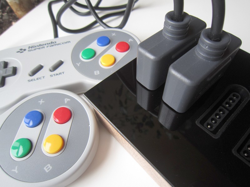
Using 2 SNES controllers and 2 NES controllers at the same time
Supporting multiple controllers at the same time is basically done by programming the Atmega8 with a different firmware. This new firmware automatically detects whether each connected controller is a NES or SNES controller. Up to 4 NES and/or SNES controller(s) can be used at the same time.
New! NES buttons have been remapped in version 1.5 and as a result it works better with RetroPie. (See buttons).
| 4x SNES and/or NES controllers to USB circuit |
| 4x SNES to USB circuit |
| SNES Controller connector |
| SNES controller extension cable |
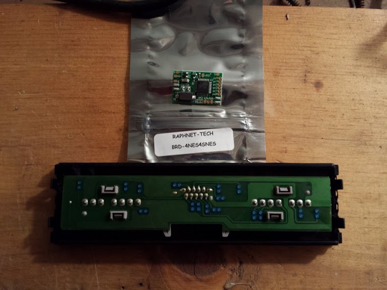
| Pre-programmed Atmega8 chips |
Pictures
Exemple 1: PCB for 4 SNES controllers:
After finding a source for SNES controller connectors (online store), I designed a circuit to receive them and tried to build an interesting enclosure for the adapter. The project is named Acrylic SNES by reference to the material the front surface is made of.


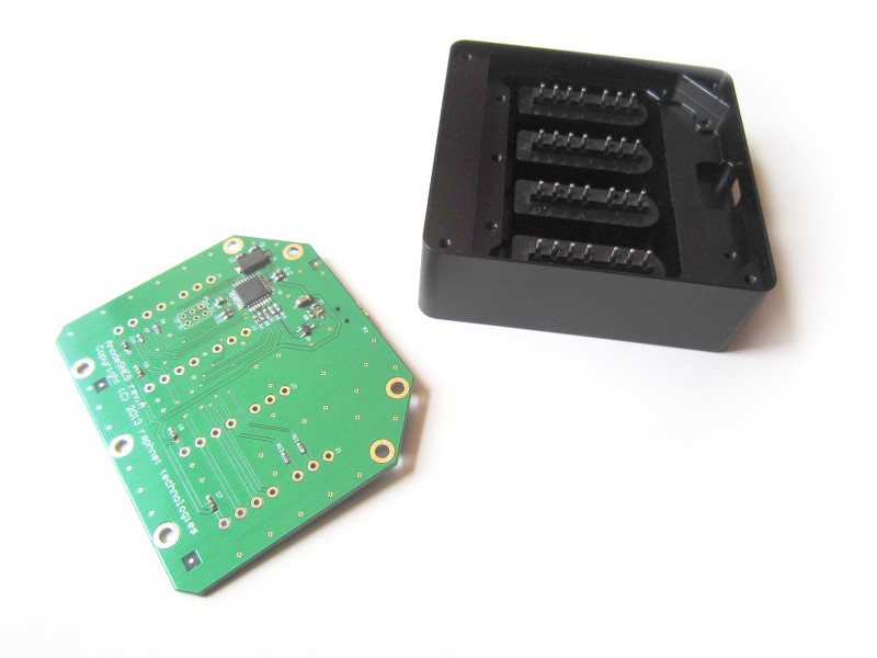
Example 2: AnodeSNES:
A 4x SNES to USB adapter built in a beautiful enclosure machined from a solid block of aluminium with a black anodized finish.For more information, vist the AnodeSNES project page.


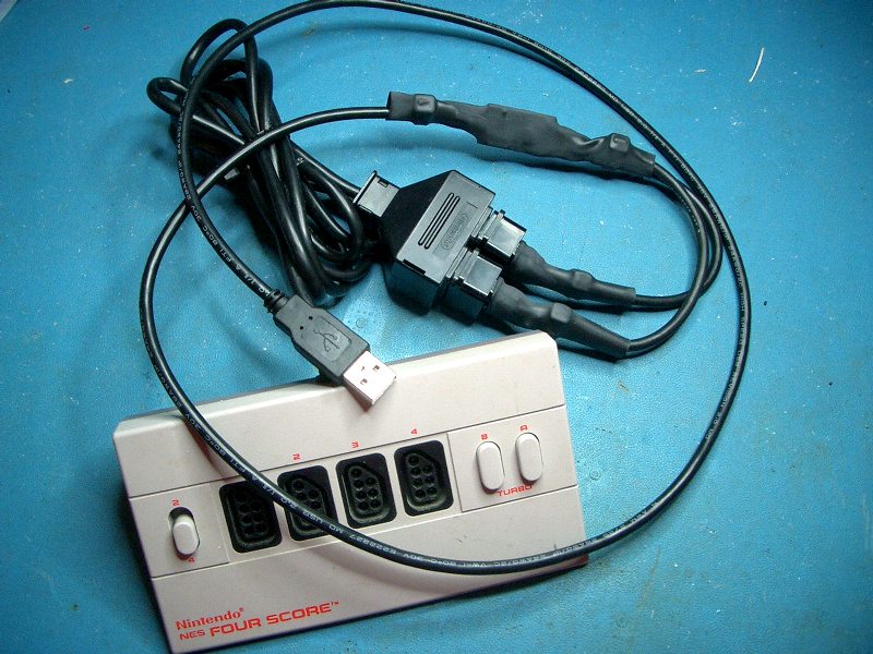
Example 3: Adaptater for the NES FourScore:


Example 4: SNES Multitap to USB


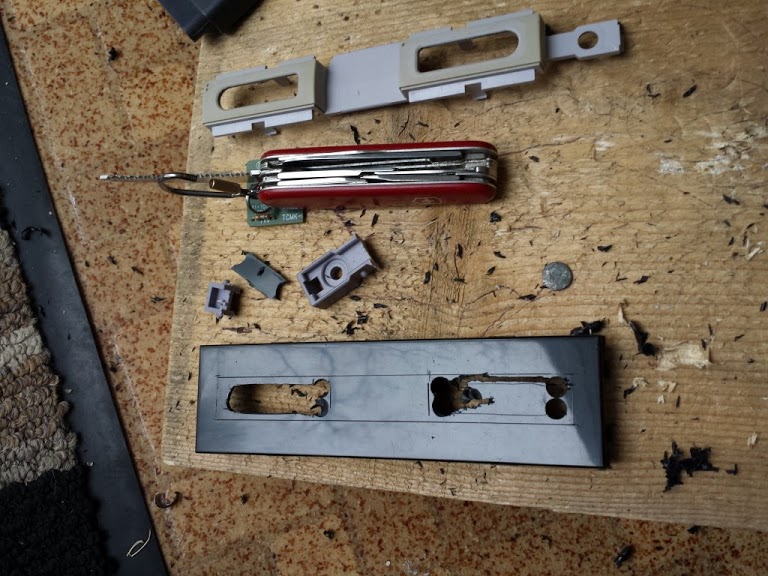
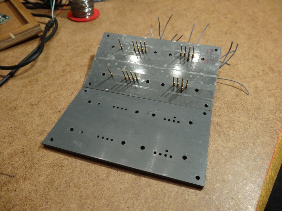
Example 5: Adapter box for 2 NES and 2 SNES controllers:

SNES controller sockets from a broken console
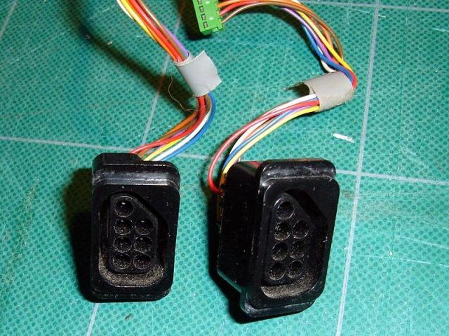
NES controller sockets from a broken console

I used the enclosure of an old NetModem which was too slow by today's standards
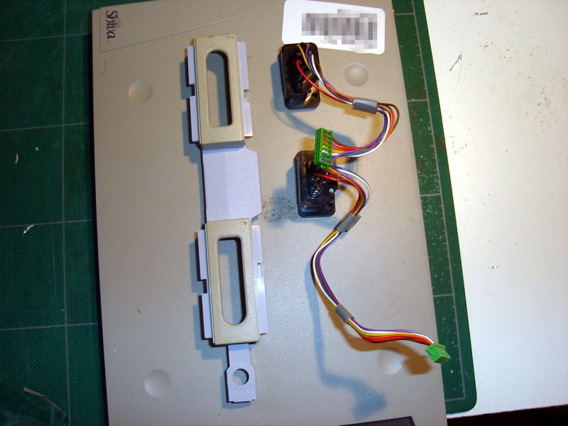
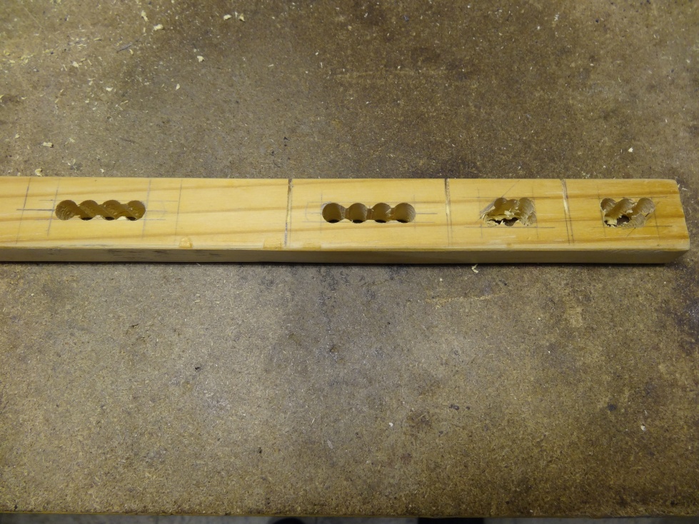
Ok, the placement looks right.

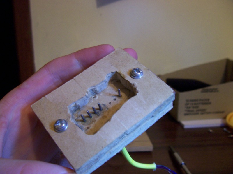
Now I know where to cut...

...I cut the holes using various techniques.

Finally done.

Making sure everything stays in place
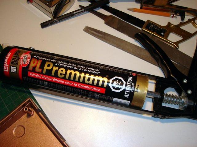
I used a renovation leftover... Polyurethane construction Adhesive.

Ok, glue applied. Now wait...

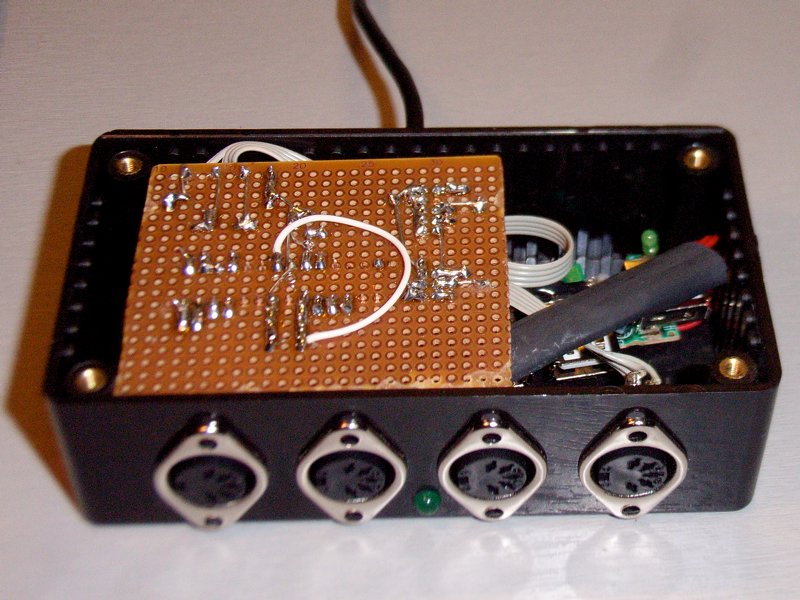
Wiring view #1

Wiring view #2

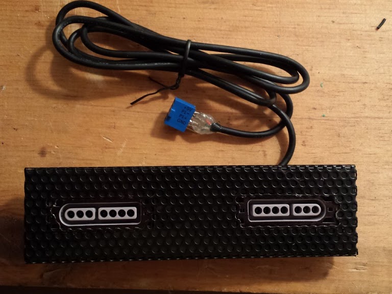
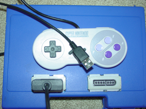
Final result 1

Final result 2
Final result 3: In use!

WinXP Joystick test screenshot
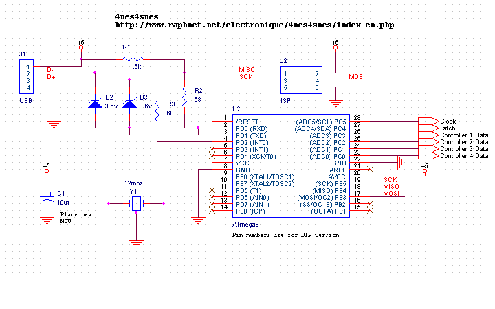
Schematic
Here is the schematic and a pinout reference for NES and SNES controllers: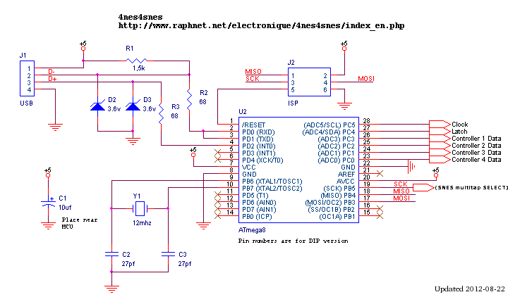
Schematic
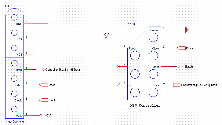
Connectors
Notes and comments: All the controllers share power, clock and latch signals. However, the data signal coming from each controller has to be connected to an unique input on the microcontroller. A ceramic resonator can be used instead of a crystal + two capacitors. Refer to Andrew Biem's schematic in the user pictures section.
Printed circuit board: You can use the printed circuit board from the initial project:
http://www.raphnet.net/electronique/snes_nes_usb/index_en.php#pcb
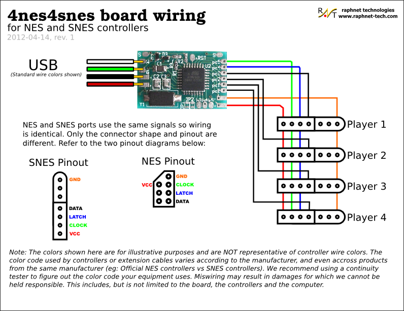
Here is also a wiring diagram for PCB rev.C:

Using multiuse pcb2:
The multiuse PCB2 board is also a good choice for this projet. Here are wiring diagrams that apply if this board is used:
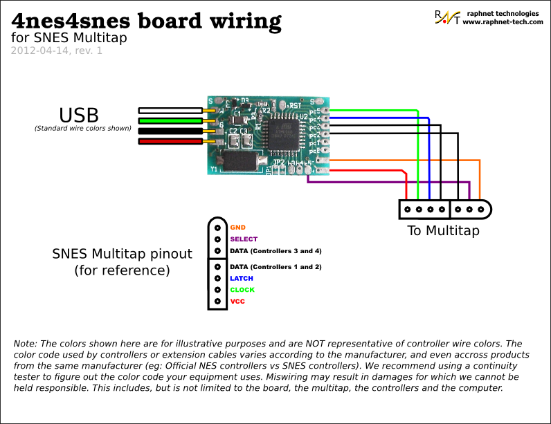
SNES Multitap support (4 players)
Starting with firmware 1.3, the SNES multitap is supported. With this peripheral, 4 controllers are read using only 2 inputs thanks to a muliplexer controlled by a SELECT signal. After latching the 4 controllers button states simultaneously using the 'latch' line, controllers 1 and 2 are read serially. This operation is then repeated, but with SELECT in a different state to access controllers 3 and 4.
Here is a multitap pinout diagram including MCU pin names for wiring:

 Available: Pre-assembled ciruits
Firmware
| Version v1.5 June 5, 2016 (Sunday) |
|---|
|
| File(s): 4nes4snes-1.5.tar.gz (84.8 KB) 4nes4snes-m168-1.5.hex (10.6 KB) 4nes4snes-m8-1.5.hex (10.3 KB) |
Show previous releases...
| Version v1.4.3 August 23, 2014 (Saturday) |
|---|
|
| File(s): 4nes4snes-1.4.3.tar.gz (84.8 KB) 4nes4snes-m168-1.4.3.hex (10.3 KB) 4nes4snes-m8-1.4.3.hex (10 KB) |
| Version v1.4.2 July 14, 2013 (Sunday) |
|---|
|
| File(s): 4nes4snes-1.4.2.tar.gz (84.7 KB) 4nes4snes-m168-1.4.2.hex (10.7 KB) 4nes4snes-m8-1.4.2.hex (10.4 KB) |
| Version v1.4.1 April 26, 2013 (Friday) |
|---|
|
| File(s): 4nes4snes-1.4.1.tar.gz (84.7 KB) 4nes4snes-m168-1.4.1.hex (10.7 KB) 4nes4snes-m8-1.4.1.hex (10.4 KB) |
| Version v1.4 April 24, 2013 (Wednesday) |
|---|
|
| File(s): 4nes4snes-1.4.tar.gz (84.5 KB) 4nes4snes-m168-1.4.hex (10.8 KB) 4nes4snes-m8-1.4.hex (10.5 KB) |
| Version v1.3 April 14, 2012 (Saturday) |
|---|
| Added SNES Multitap support (4 player mode). Only tested with Naki Tribal Tap. |
| File(s): 4nes4snes-1.3.tar.gz (83.8 KB) 4nes4snes-1.3.hex (11 KB) |
| Version v1.2 May 2, 2009 (Saturday) |
|---|
|
| File(s): 4nes4snes-1.2.tar.gz (92.5 KB) 4nes4snes-1.2.hex (10.1 KB) |
| Version v1.1 April 18, 2007 (Wednesday) |
|---|
| First public version. Used proprietary Objective Development License (modified GPL). See License.txt. |
| File(s): 4nes4snes-1.1.tar.gz (70.2 KB) 4nes4snes-1.1.hex (8.7 KB) |
 This project is also available on GitHub!
To request features, report issues or contribute, you may send me an email or use the GitHub repository:
https://github.com/raphnet/4nes4snes
Using .hex files
- Atmega8: The *-m8-*.hex or *.hex files prior to version 1.4 are for programming an Atmega8. The fuse bytes for Atmega8 are: high byte = 0xc9, low byte = 0x9f.
- Atmega168: The *-m168*.hex files are for programming an Atmega168. The fuse bytes for the Atmega168 are: high=0xd5, low=0xdf, extended=0x01
For informations about how to program an AVR MCU, visit my AVR programming page.
Source code (.tar.gz files):
Unless otherwise noted, the source code is released under the terms of the GPLv2 License. See License.txt more information. The project compiles with avr-gcc under linux.
4nes4snes-1.2.tar.gz
Note: If you are using the source code release under Linux, look at the Makefile. It has a flash and a fuse target which uses uisp to program the flash and fuses.
Buttons
Staring with version 1.5, the NES buttons have been reassigned to match SNES buttons. This makes it possible to switch controller type without reconfiguring anything. Works great for RetroPie...| USB | SNES Button | NES Button (before v1.5) | NES Button (since v1.5) |
|---|---|---|---|
| 0 | B | B | |
| 1 | Y | ||
| 2 | SELECT | SELECT | |
| 3 | START | START | |
| 4 | A | START | A |
| 5 | X | SELECT | |
| 6 | L | A | |
| 7 | R | B |
Note: USB buttons are numbered from zero. If you are under Windows, you will have to add 1 to the numbers in the above table.
User pictures
I enjoy seeing how others build my projects. It also makes good assembly examples. Please send me your pictures and I'll add them here.August 26, 2017 (Saturday)
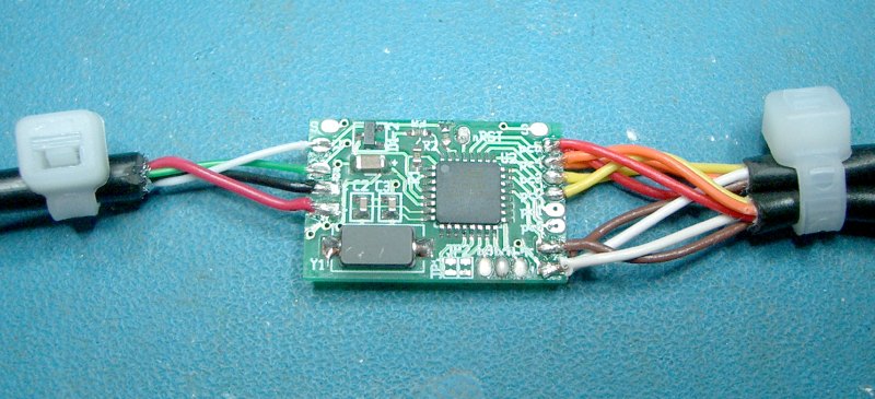
Robson Couto built the following adapter for two SNES controllers. He also presents on his blog a derived project adapted to run on a low cost USBASP AVR programmer.

July 10, 2016 (Sunday)
Sebastian installed a Raspberry Pi in a NES case and used a 4nes4snes circuit board for the controllers.


December 26, 2014 (Friday)
Michael Bazzinotti aka bazz built a press-fit enclosure to go with my acrylic cover and PCB. More information on this project and on the enclosure design approach can be found on his website.


November 14, 2014 (Friday)
Eduard build an adapter for two NES controlles using the connectors from a console:


January 29, 2014 (Wednesday)
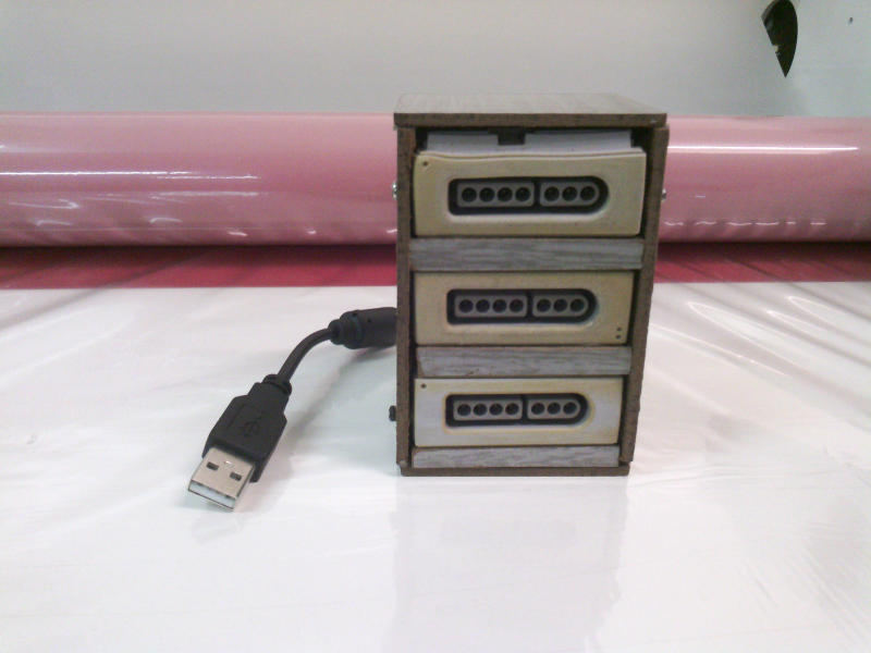
Josafá Siqueira from Brazil sent me the following pictures of a 3 player adapter he built.


January 25, 2014 (Saturday)
Ákos sent me this picture of an Hudson soft multitap he converted to USB using this circuit. He adds: "I didn't need to damage the multitap at all! Just unplugged the factory cable, made my own, stuffed everything inside and it works.". This confirms that multitap support, present since firmware version 1.3, works with mutltaps other than the Naki Tribal Tap I tested with.

January 7, 2014 (Tuesday)
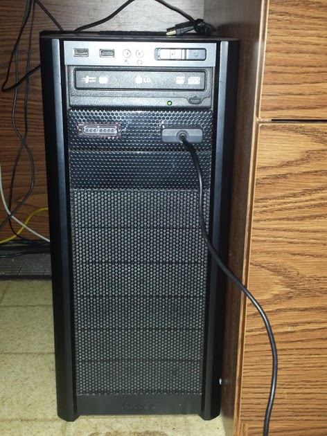
Daniel Baer sends me the following pictures of an adapter he built to fit one of his PC 5 1/4" drive bay. The USB cable connects directly to one of the USB headers on his ASUS motherboard. He and his wife can now play Dr. Mario on Arch Linux with the Higan emulator.


May 3, 2013 (Friday)
Pascal and Nicolas Roux sent me pictures of an adapter using home made connectors inspired by the work of Declan Williams (see above) and explains: "We took two plastic plates which we temporarily stuck together (using double face tape) for drilling. We then took them apart to install the contacts (with wires pre-soldered to prevent melting the plastic). Then we prepared the protections (wood) to surround the contacts and wired-in the circuit (and installed the protections using screws)".


January 9, 2013 (Wednesday)
Alex (here is his blog) created a through-hole PCB, and provided the Eagle schematic and board files:


Eagle schematic: V-USB_4SNES_Mame_Panel_Atmega8.sch
Eagle pcb: V-USB_4SNES_Mame_Panel_Atmega8.brd
August 14, 2011 (Sunday)
Thomas Lapauw built an adapter for two SNES controllers. He also added a power LED:


June 25, 2009 (Thursday)
Jeff Erbrecht has installed the circuit inside a SNES multitap. It was necessary to remove some components from the original Multitap circuit since they caused some problems.


June 17, 2008 (Tuesday)
Tim Wylie built this 4 controller adapter (2 Snes and 2 NES) using the pre-assembled circuit:

October 4, 2008 (Saturday)
Craig O'Connor sent me the following pictures:


May 31, 2008 (Saturday)
Lucas Romero, from Germany, built this project for being able to use SNES pads with his laptop which has no parallel port. He named his project "RetroBox" and added an internal USB Hub with a 2GB USB-Stick so he always has his favorite SNES and MAME roms with him:


Gunther Baumgartner, from Germany, has installed the circuit inside a NES Four Score:

Andrew Biem, from Whidbey Island, Washington, USA, sent me the following pictures. Notice that he used a ceramic resonator instead of a crystal + two capacitors. He also provided an updated schematic.


Declan Williams (16 years old), from Australia, sent me the following pictures. Notice he found a pretty clever way to build his own SNES-style connectors:


Steve and Andi, from Austria, sent me the following pictures:


References
This page contains documentation about the Snes controllers 'protocol':Sci.Electronics FAQ: Super Nintendo Entertainment System: pinouts & protocol
I use the software USB driver from Objective Development. For more information, visit their site:
http://www.obdev.at/products/avrusb/index.html
This was useful for understanding how Windows/Direct Input interprets the report descriptor and why some axes were not recognized by Windows 98:
http://www.microsoft.com/whdc/device/input/hidgame.mspx
Disclaimer
I cannot be held responsible for any damages that could occur to you or your equipment while following the procedures present on this page. Also, I GIVE ABSOLUTELY NO WARRANTY on the correctness and usability of the informations on this page. Please note, however, that the procedures above have worked in my case without any damages or problems.Now you cannot say that I did not warn you :)