Dreamcast controller to USB build log [in progress]
About this project and goals
I have received many requests and while I had been looking forward to the challenge of building this adapter, due to other not less interesting projects, it took a very long time before I finally began working on it. This time, following a suggestion and contrary to my habit of only posting projects in their completed form with the source and schematics, I decided to create a build log page I would update as things progress.Here are the features I am aiming for:
- Necessary: Support Dreamcast controllers
- Necessary: Act as an USB HID joystick
- Nice to have: Support other peripherals
- Nice to have: VMU communications
Step 1 : Documentation, wiring and validation
September 28, 2013As a starting point, I used a website with documentation (hardware and software) about the Dreamcast I already know about:
Dreamcast Programming: http://mc.pp.se/dc/
- Wiring and controller data: http://mc.pp.se/dc/controller.html
- Maple bus (software): http://mc.pp.se/dc/maplebus.html
- Maple bus (hardware wire protocol): http://mc.pp.se/dc/maplewire.html
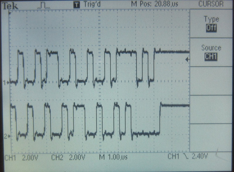
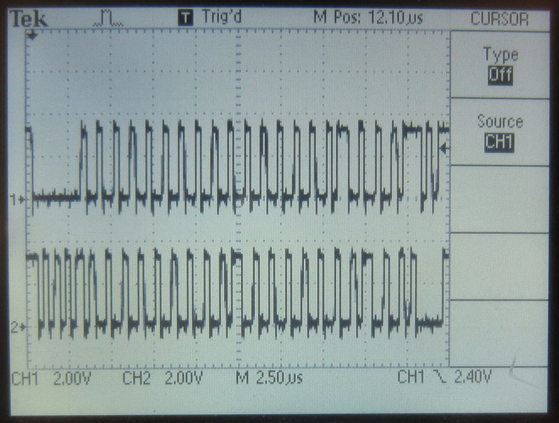
So to begin, I wanted a few scope traces of the communication between my Dreamcast console and a controller. Yes, even if timing diagrams are available at http://mc.pp.se/dc/.

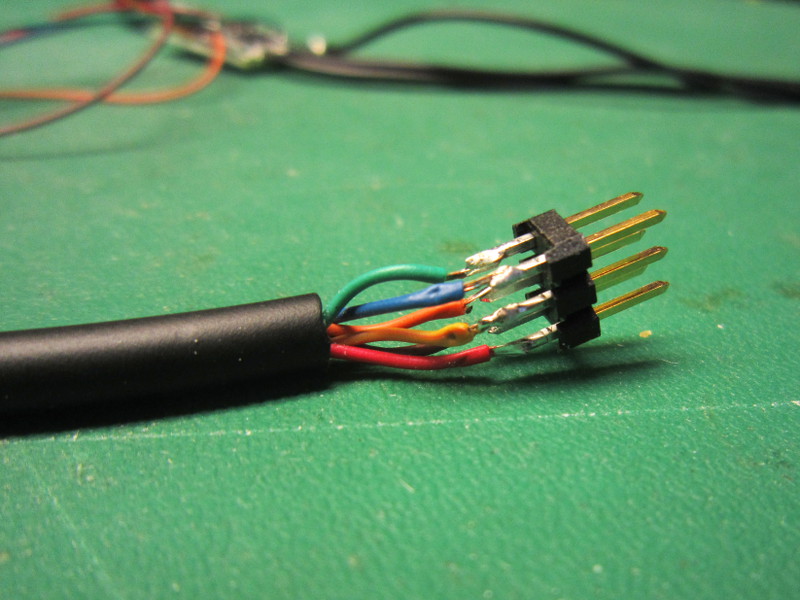
Extension modified for accessing signals
| pin# | Color | Function | AVR signal chosen |
|---|---|---|---|
| 1 | Red | Data | PC0 |
| 2 | Brown | +5v | |
| 3 | White | GND | |
| 4 | Blue | SENSE | |
| 5 | Yellow | Data | PC1 |
| MÉTAL | Black |
Now I just had to install the Dreamcast and the scope, so I did.
A very important point to confirm was the supply voltage. Is it really 5 volt? I saw pages in the past contradict each other on game controller supply voltages so I am careful. But the supply really is 5 volt. However, communication is at 3.3v! On this point, this page is not accurate. (Citation: «At the beginning of phase 1, pin 1 is always high (+5V), and pin 5 is always low (0V).»)
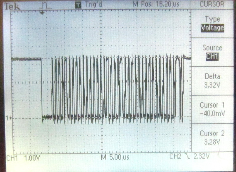
Request
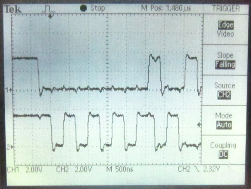
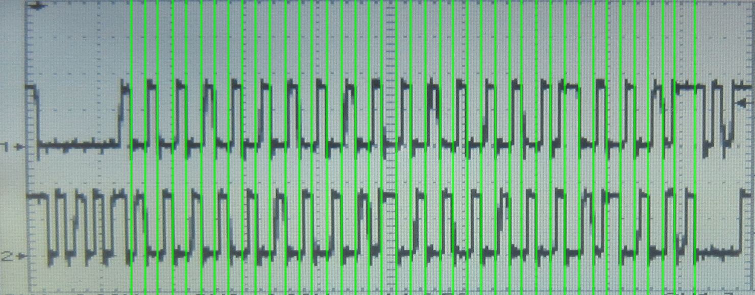
Zoom on request
Request and answer
In order to use the correct supply and communication voltages, I will use my multiuse PCB2 circuit, configured with a 3.3 volt regulator, the MCU running at 3.3v with a 12Mhz crystal. The controller will be powered directly from the USB bus 5 volt rail.
To achieve this, I changed where 0 ohm resistors are installed at the back of a multiuse PCB2 circuit, I wired an USB cable and an ISP connector for programming the MCU. I also wired a DB9 connector to expose the power and data signals for the controller.
I wired a DB9 to my Dreamcast extension so that it still works as an extension. By doing this, it will be easy to disconnect my adapter circuit when I will need to look at the Dreamcast communicating with a controller again later.
ISP connector
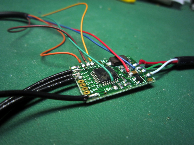
Multiuse PCB 2
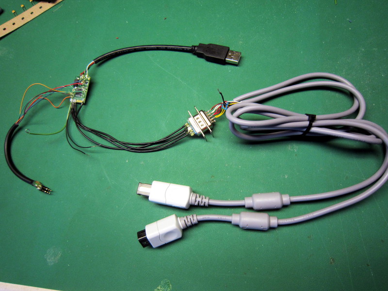
Overview
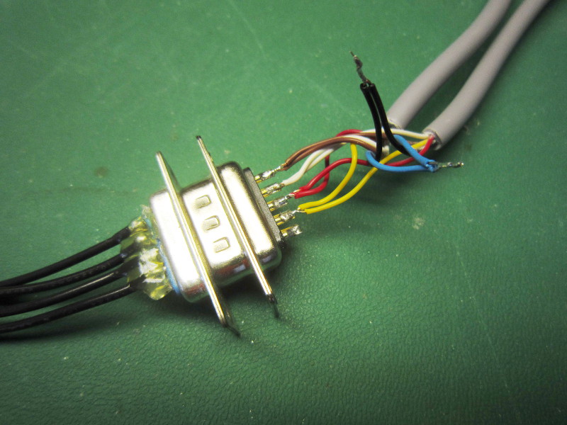
DB9
The DB9 is wired as follows:
| Circuit side | |
|---|---|
| Pin | Signal |
| 1 | +5v |
| 2 | GND |
| 3 | PC0 |
| 4 | PC1 |
| Extension side | |
|---|---|
| Pin | Couleur |
| 1 | Brun |
| 2 | Blanc |
| 3 | Rouge |
| 4 | Jaune |

Test wires
I connected everything and the VMU inside the controller powered up properly (Momentary black screen and a beep, which I think means the battery is dead). This is exactly what happens when I try it on a real Dreamcast. So everything looks good.
Now, the real fun can begin!

Ready for programming
Step 2 : Frame transmission
October 6, 2013I began writing the firmware. First step, implement a transmission routine in assembler to achieve a timing identical (or very close) to what is shown on http://mc.pp.se/dc/, but also to what I see on my Dreamcast bus with the scope.
The AVR MCU is clocked at 12 Mhz, which means 12 cycles is 1us. Each transmission phase (see reference) lasts 500ns, which leaves us only 6 cycles.
There is not enough room for a naive implementation. Too many cycles are lost branching to conditionally set the pins according to the data we want to send. Also, we must keep track of how many bits we sent in order to load a new value when necessary, which means an extra delay every 8 bits. And finally, the total number of bytes sent must also be tracked.
It would be possible to unroll the code to save cycles by getting rid of all this overhead. In order to still be able to send a variable quantity of bytes, the code code could be unrolled for a very large quantity of bytes. Then, to transmit a given quantity, we could jump at a calculated distance from the end.
But unrolling loops more than 100 times in assembler is a tedious task if done manually, so I would write a script to do it for me. But as I would like to successfully communicate with a controller as soon as possible, I do not want to do this now. I will waste time on a better implementation later.
For now, I implemented a transmission routine which requires the data to be formated in bytes (1 byte of memory is used by bit transmitted). It is memory hungry, but the transmission routine is simplified to become a simple loop. Still, because there is a counter, the code is 1 cycle too long. 83ns is therefore lost for each pair of bits transmitted. Ideally, I would unroll this loop, but the good news is that the controller does not care. After all, this is a synchronous protocol!
	// Not shown
	Initialisation of the r19 counter
	Initialisation of constants r20 and r21

	ld r16, z+      // 2  load phase 1 data
next_byte:

	out %0, r20     // 1  initial phase 1 state
	out %0, r16     // 1  data
	cbi %0, 0       // 1  falling edge on pin 1
	ld r16, z+      // 2  load phase 2 data
	dec r19         // 1  Decrement counter for brne below

	out %0, r21     // 1  initial phase 2 state
	out %0, r16     // 1  data
	cbi %0, 1       // 1  falling edge on pin 5

	ld r16, z+      // 2
	brne next_byte  // 2
I was now confident the timing was good enough, so I used the documentation and built a frame to request data from a controller. But the controller was not answering so I put the scope on the Dremcast again to compare. But it did not help, I did not find anyting wrong.

Dreamcast Sync
Dreamcast End
Dreamcast request
Decoding the request
Anyway, reading the documentation again, I finally understood the byte order. Each group of 4 bytes must be reversed. So [ 1 2 3 4 ] [ 5 6 7 8 ] must be transmitted as [ 4 3 2 1 ] [7 6 5 4 ]. As the Dreamcast hardware does this automatically, most of the documentation is written in the normal order. I had not understood correctly.
So now the controller was answering, but I did not see any bits changing when I moved the joystick. In fact, I was not sending the right request. Command code 1 (Request device information) does not return the state of the controller. According to the documentation, I should rather use command 9 (Get Condition).
I updated my test program to repeatedly send command 9 (Get condition) instead of command 1 (Request device info.). But the controller did not answer. I notice command 9 requires an argument to specify we want to talk with a controller. I update the code, still no answer…
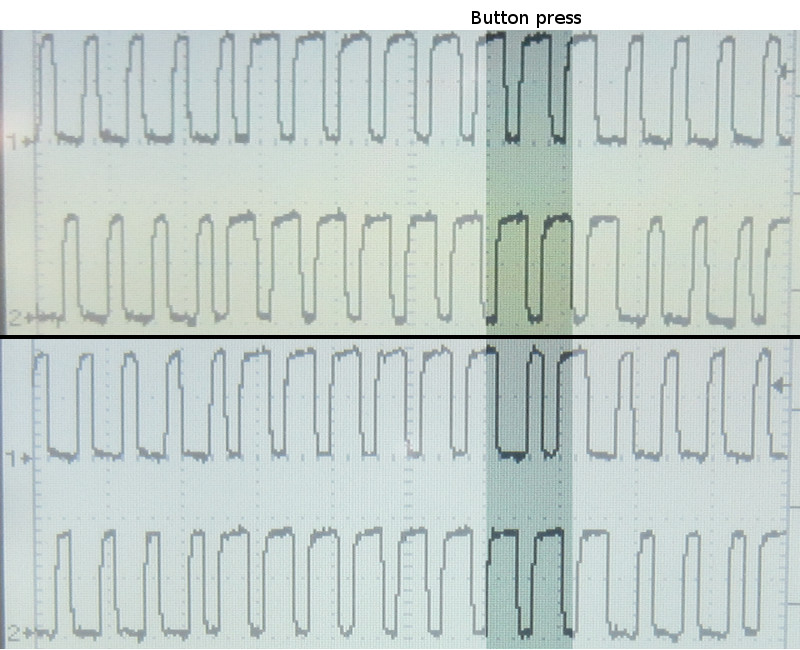
A bit changing according to a button
Now that everything was working well, I tried slowing transmission down. Sending the data 4 times slower still works fine. I would probably be possible to actually send the frame in C, or in simpe assembler! But I think that for compatibility, in particular with 3rd party controllers, it is probably safer to try as hard as possible to send at the speed a real Dreamcast does anyway.
Status: Transmission is a success. But looking at the result on a scope is obviously not very useful, so the next step is implementing reception. More fun to come!
Step 3 : Frame reception and USB
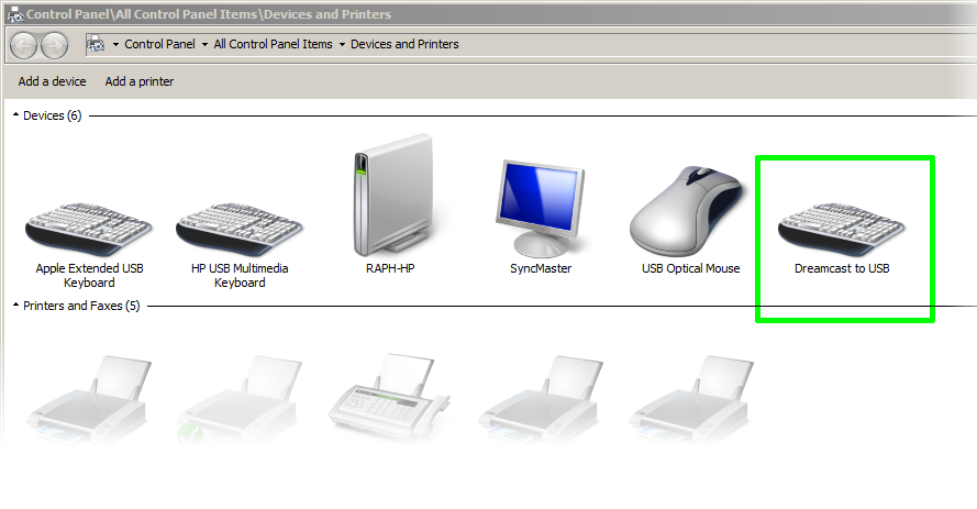
October 13, 2013My multiuse PCB2 circuit does not have a serial port, so for displaying the data received from the controller, USB is the most logical choice. So I downloaded the latest V-USB and setup the environment required to act as a standard HID joystick. Nothing new for me here, so soon after, Linux was detecting the adapter:

Now that USB communications where arranged for, I implemented the logic required to send a «request device information[1]» packet at least once to the controller before starting to emit repeated get condition[9]» requests. I was now ready to write the data reception code.
According to the timing diagrams from mc.pp.se, data is held stable for a minimum of 250ns. At 12MHz, this is 3 MCU cycles. Reading the port ("in" instruction, 1 cycle) and writing the value to memory ("st" instruction, 2 cycles) requires exactly 3 cycles. Very tight.
Polling for the falling edges, counting and packing the bits is of course out of the question here. So using a script I generated a long assembler sequence that simply read the port and store the value to memory. Aftewards, we can take our time analysing the received data to detect the start of the frame, detect falling edges, extract the bits, pack bytes and detect the end of frame. Here is what the long reception block looks like:
	; Z points to the receive buffer
	; PINC is the pin level register
	;
	in r16, PINC  ; 1 cycle
	st z+, r16    ; 2 cycles
	in r16, PINC  ; 1 cycle
	st z+, r16    ; 2 cycles
	....
	Repeated 640 times.
Although this code is very fast, it is also very memory hungry. 640 bytes out of the 1024 we have on hand. Unfortunately, supporting memory cards won't be possible.
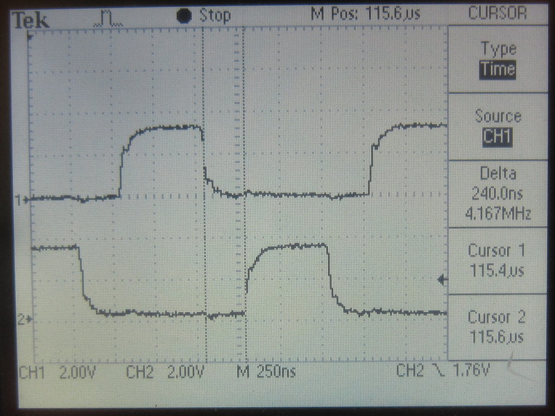
Only 240ns of stable data…
I then implemented packet verification using the LRC embedded in all maple bus packets (LRC is a XOR of all bytes, sometimes called "checksum"). By doing so, packets with errors can be ignored. But since a majority of packets (At least 80%, I reckon) were then rejected, the joystick and buttons were not responsive at all. Not acceptable for gaming, nor anything else I would say…
So I had no choice but to increase the clock from 12 MHz to 16 MHz. Each MCU cycle now took only 62.5ns (was 83.3ns). The reception code was now sampling at 187.5ns intervals which meant there would always be at least one sample taken when the data is stable. And indeed, the errors stopped and the controller became perfectly usable!
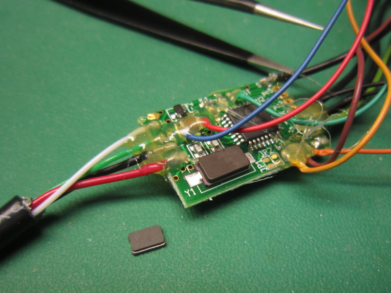
12MHz crystal to change
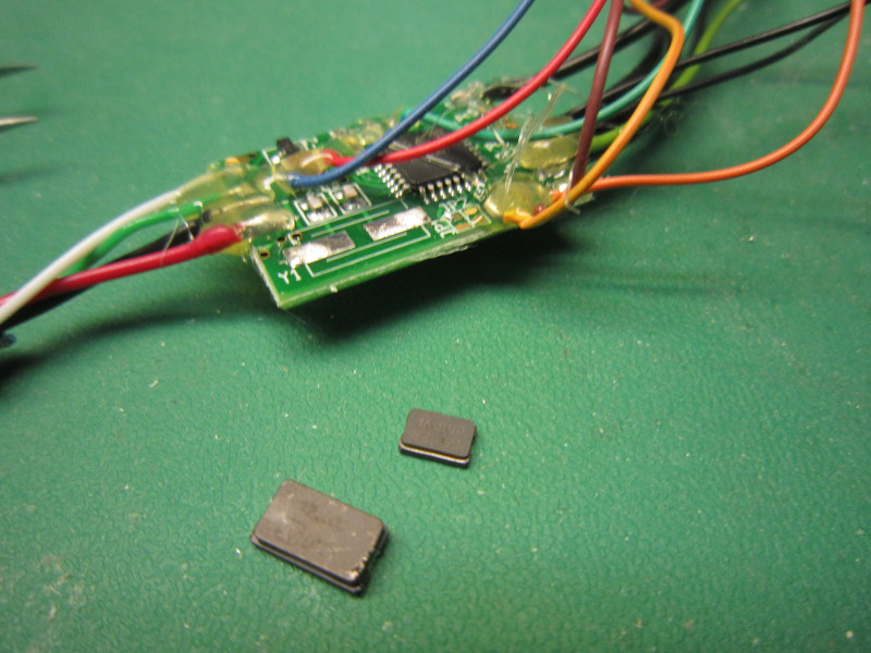
Change in progress

New 16 Mhz crystal
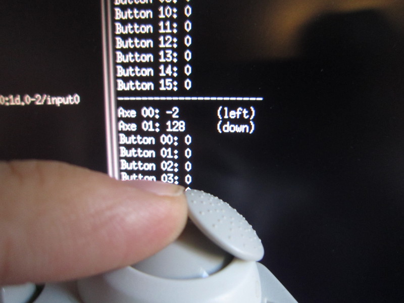
It works!
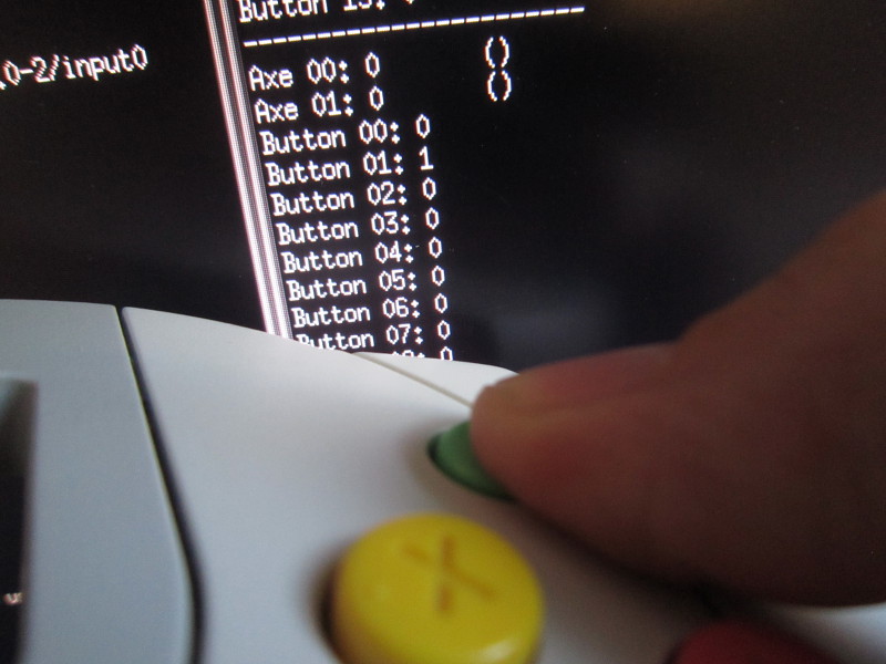
It works!
Now, for an Atmega168 on a 3.3v supply, 16 MHz is outside the documented safe operating area. While it does seem to work, I do not like doing that kind of design. So I modified my PCB to supply 5 volt to the MCU. To communicate at 3.3 volt, the idea was to control the pin direction, alternating
With an 1.5k resistor
Unfortunately, this is not a simple I2C bus running at 100kHz on a short distance. Dreamcast controller communications require a much higher data rate, approximately 10 times faster. The voltage rose way too slowly and could not even reach 2v before being driven low again. This is probably due to the cable capacitance, but maybe also to the controller input circuitry. With the 1.5k resistor, this forms an RC circuit. By using a resistor with a lower value, rise time was improved but I was not able to obtain an acceptable rise time. When the value got too low, the MCU stopped being able to drive the line to a logic zero due to current, as shown in the following pictures:
Resistor too low
I also tried slowing down transmission, but I did not receive an answer from the controller. Maybe it was too slow, or maybe the controller did not like the slow rise time. But even if this had worked, it felt like trading a risk (overclocking) for another (risk of incompatiblity).
In short, the adapter now works. However, the MCU is slightly overclocked. So far I see no ill effects, but testing will be necessary. Please contact me if you would like to help testing. But even with testing, I know I will always have doubts. If there is demand, I will design a circuit using a level translator, for instance the SN74AUC2G07.
Next step: Project page in the electronic section with schematics, hex files and source code.
November 2, 2013: Here is the project page.
Mouse support
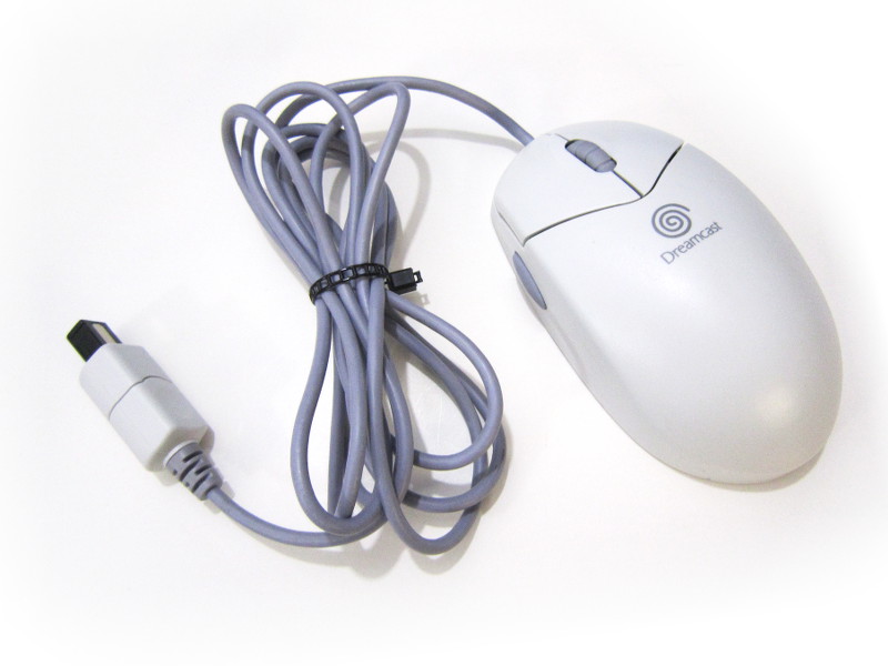
The Dreamcast mouse
This week-end I decided to add support for the Dremcast mouse I had received during the week. Electrically it is the same as a controller so I only had to work on my firmware.
The mouse is queried using the "Request device information [0x01]" command and returns a data structure indicating it is a mouse (The first 32 bit workd contains the 0x200 value). Then the "Get condition [0x09]" command returns button status and motion data.
The following page details how the returned information is structured:
http://mc.pp.se/dc/mouse.html.
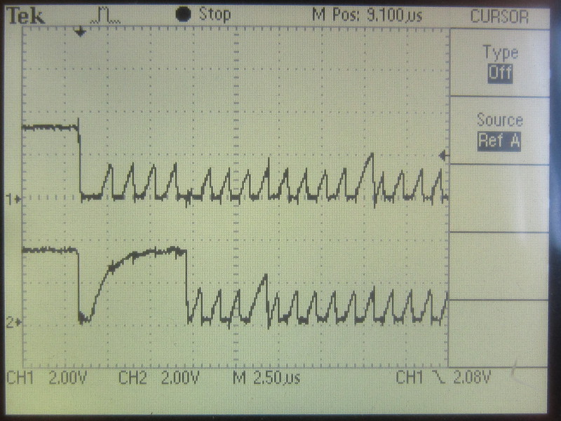
I do not know what Sega was planning, but the structure supports 32 buttons and 8 axes. And each axe is reported using 16 bits. This is more than a normal mouse needs and represents a lot of data. So much data that it is not even possible to receive everything using my memory hungry (but fast) algorithm. The transmission pause occuring after a few bytes are transmitted does not help either:

The lower trace represents the state of a free pin I use for debugging. The first pulse occurs when the reception code starts running and the second one when it ends. Reception is ending way too early.
I wanted to increase the length of the reception code, but the MCU does not have enough memory to store the additional data this would represent. But I nontheless managed to support the mouse, but not perfectly: The wheel does not work since the wheel data is in the second block. Also, the LRC cannot be checked since it is at the end of the packet. If a communication error occurs, we won't know.
Conclusion: The mouse will only be partially supported as long as the adapter will be based on my simple multiuse-pcb2 circuit.
3rd party controller support
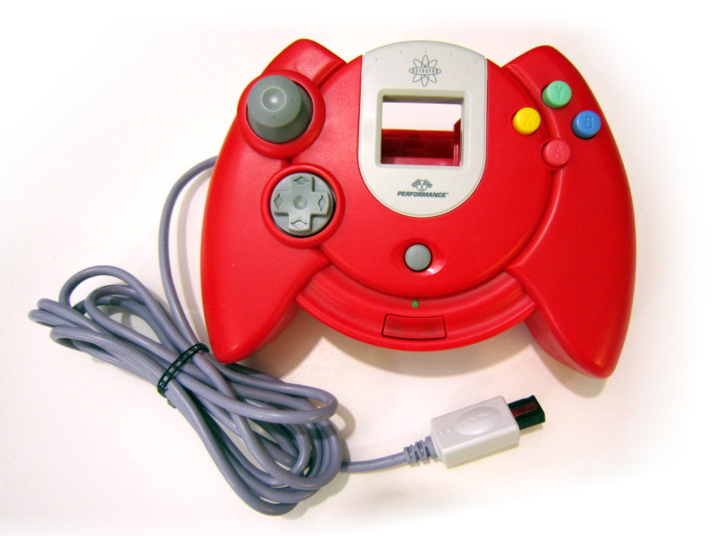
Performance P-20-007
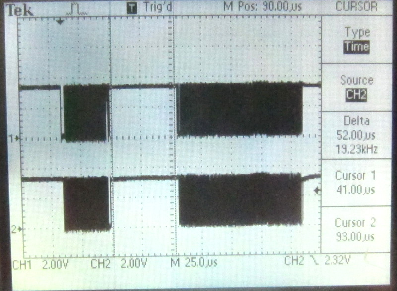
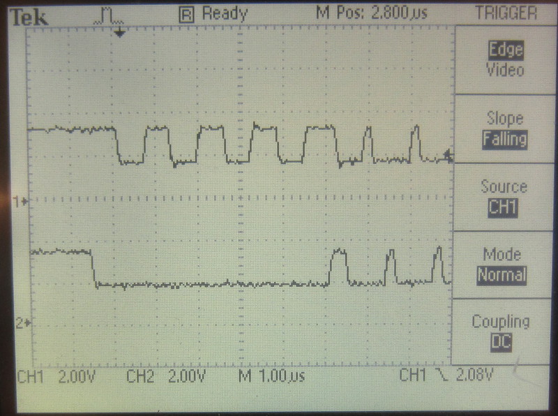
I managed to find a 3rd party Dreamcast controller I bought years ago. I tested it right away but it did not work... So I fired up the scope to look at the signals. The controller was actually answering the requests correctly. Only, it was answering much slower than an official Sega controller. 56μS vs. 159μS:
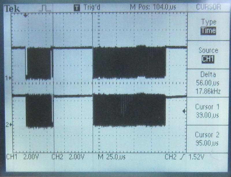
Quick answer
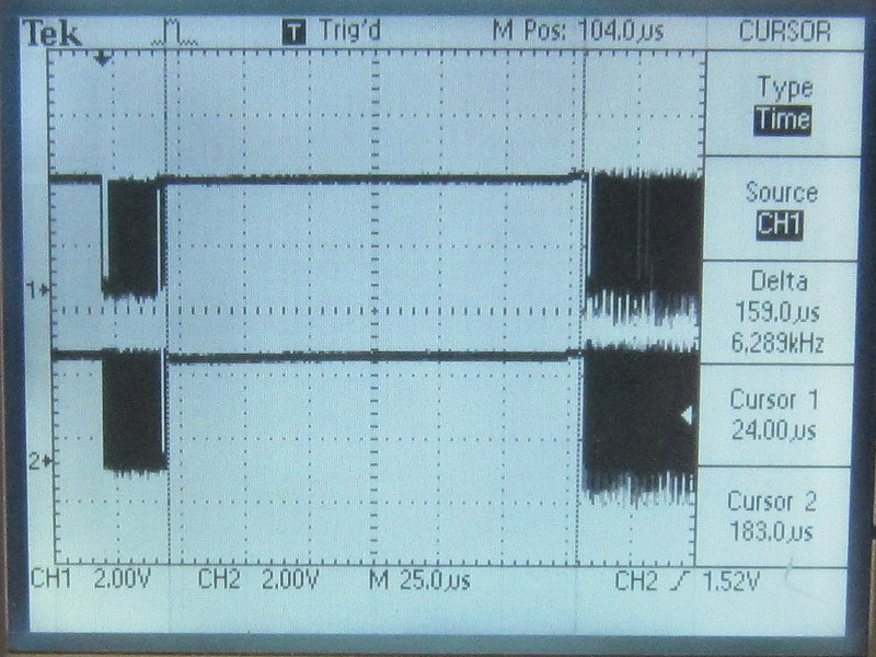
Slow answer
The problem was simple: My reception code was not waiting long enough for the answer. A quick code modification later the controller was working.
This improvement is available in firmware release 1.1.1.
Keyboard support
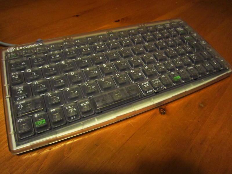
HKT-4000
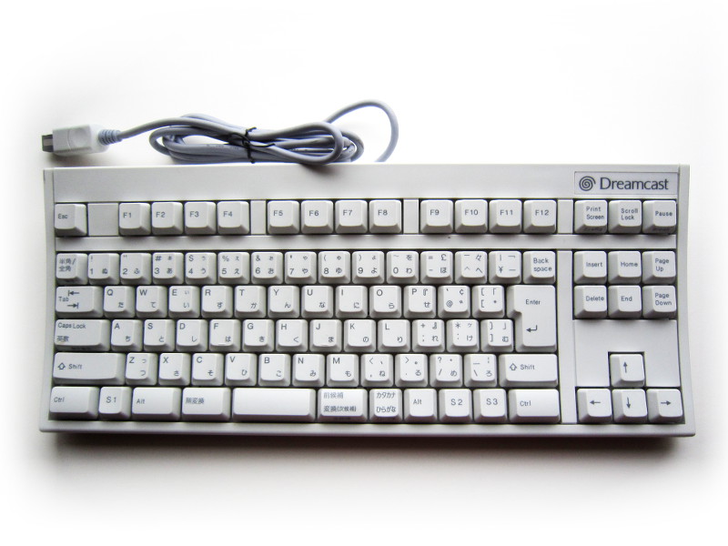
HKT-7600
Supporting the keyboard was quite easy. The auto-detection logic using the « Request device information [0x01] » command was already in place since I added mouse support.
I was expecting I would have to create a keycode translation table, but no, the Dreamcast keyboard uses the same codes a normal PC keyboard does!
Compare for yourself:
- http://mc.pp.se/dc/kbd.html (Dreamcast keyboard documentation)
- USB HID Usage Tables, section 10. (Keyboard/Keypad Page [0x07]).
Those keyboards have a Japanese layout so the PC must be configured accordingly. Otherwise, many keys, in particular the symbols around the return key, will not produce the corresponding characters. Here are a few screenshots under win7:

LCD support
November 9, 2013I thought it was a bit sad that the VMU screen stayed blank so I did something about it and added code to display a static image.
Please let me insist on the fact that this only displays an image hardcoded into the firmware. The image cannot be changed, unless you recompile the project. It cannot be changed through USB. In other words, an emulator cannot control the LCD using this feature.
To display an image, a single packet with 192 bytes of data for the LCD has to be transmitted which means I could not use my fast (but memory hungry) transmission routine. But since the maple bus is synchronous, transmitting at a lower pace is fine. I therefore wrote a C version. I'm still using the asm version everywhere else.
The image displayed will be changed with each release.

Startup banner
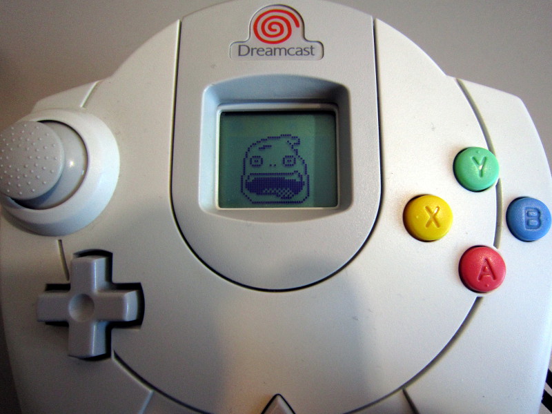
Version 1.2 image