Circuit for USB game controller with 12 inputs (8 buttons + 4 directions)
Project overview
- Home-made Arcade style controller and small arcade cabinets
- Simple controller (1 wire per button) to USB. Eg: Neo-Geo, Atari...
- Using appropriate software on the PC side, the inputs can be used for other purposes. Eg: Switches, limit-switches, alarms... A cleaner solution than modifying an existing game controller
On this page, you'll find out how to build such a circuit using a microcontroller. The firmware implements a standard USB joystick with 4 directional buttons and 8 general purpose buttons.
 Depending on your skills, you can build the circuit on a breadboard using thru-hole components or
build the surface-mount version using my small multiuse PCB2
circuit board. I also sell ready to use circuits and pre-programmed Atmega8 chips (in DIP package only). Visit
my online shop for more details.
Depending on your skills, you can build the circuit on a breadboard using thru-hole components or
build the surface-mount version using my small multiuse PCB2
circuit board. I also sell ready to use circuits and pre-programmed Atmega8 chips (in DIP package only). Visit
my online shop for more details.
No drivers required!
That's right, since the USB standard defines device classes. I'm using the human input device (HID) which allows me to tell to the computer that the connected USB device is a joystick and has 2 axis and 4 or 8 buttons. Another nice thing about this is that the adapter should work with all operating systems supporting HID devices. (I tested and it works at least on Win98, Win2K, WinXP and Linux)
This project uses an ATmega8 microcontroller from Atmel. This microcontroller does not support USB in hardware so I used the software-only usb driver from Objective Development. This driver allows an AVR microcontroller such as the ATmega8 to talk USB with minimal external components. As a result, the interface can be built cheaply and easily
 Ready to use circuits available
Schematic
Here is the main schematic: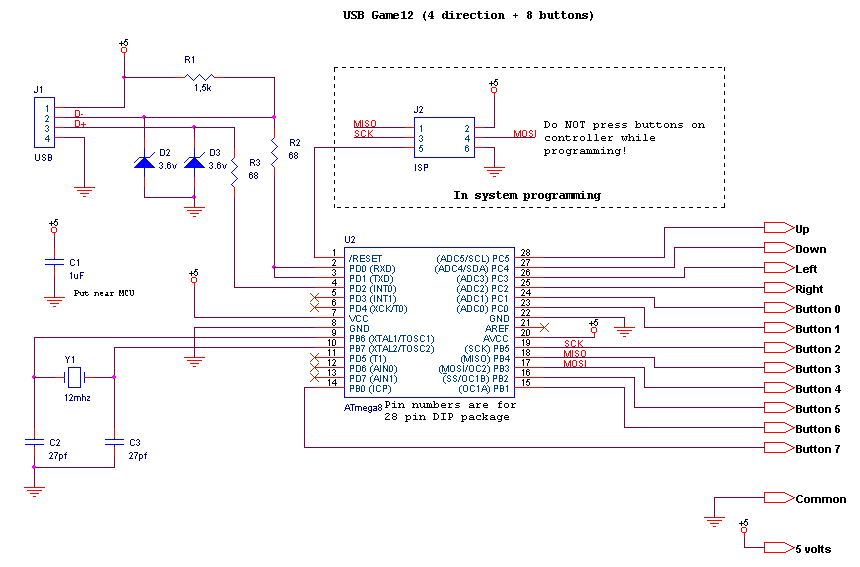
|
And here is a wiring example: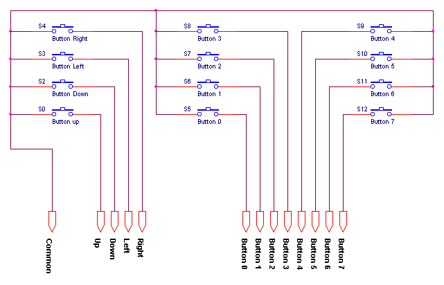
|
Additionally, a wiring table for NeoGeo controllers is shown lower on this page.
Component list:
| Ref | Description |
|---|---|
| U2 | Atmega8 microcontroller. ATMEGA8-16PC, ATMEGA8-16PI, ATMEGA8-16PJ or ATMEGA8-16PU. Dont use an ATMEGA8L-*, the 12Mhz clock would be too high. |
| R1 | 1.5k resistor. Ordinary carbon film 1/4 watt resistors will do. |
| R2, R3 | 68 ohm resistors. Ordinary carbon film 1/4 watt resistors will do. |
| D2, D3 | 3.6 volts zener diodes. |
| R4 | Do not install, not used anymore. |
| D1 | Do not install, not used anymore. |
| Y1 | 12 Mhz crystal. |
| C2, C3 | 27 pf capacitors. If the crystal datasheet recommends another value, use it instead. |
| C1 | 10uf capacitor. Install it near the ATmega8. |
| JP1, JP2 | Jumpers. You can also use dip switches, ordinary switchs or solder bridges. |
| J2 | 6 pin header, 2.54mm spacing. Needed for programming the ATmega8. |
For the USB connection, just strip the USB cable and solder the wires directly to the board. USB uses standard wire colors:
| Color | Description | |
|---|---|---|
| Red | +5 volts | |
| Black | Ground | |
| Green | D+ | |
| White | D- |
Programming
A microcontroller is a component which must be programmed in order to do something useful. So here is the hexfile which must be flashed into the microcontroller:usb_game12-1.0.hex
Many microcontrollers have what is called 'Fuse bytes'. In the case of the ATmega8a, there are two bytes: The high byte, and the low byte. Those bytes are used to configure some aspects of the microcontroller. What type of clock to use? Crystal? Resonator? Internal RC clock? Allow programming via ISP? It's very important to set the fuses to the right values. Using the wrong values can render your MCU unusable.
For this project, here are the appropriate fuse values:
high byte = 0xc9, low byte = 0x9f
For details about how to program an AVR, visit my AVR programming page.
Source code
The source code is released under the GPL license and compiles with avr-gcc. To prevent conflicts, please do not distribute modified version where the USB report descriptor has been modified without replacing the USB Vendor ID and Product ID by yours.usb_game12-1.0.tar.gz
 This project is also available on GitHub!
To request features, report issues or contribute, you may send me an email or use the GitHub repository:
https://github.com/raphnet/usb_game12
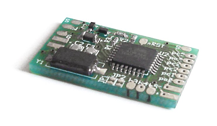
PCB for surface-mount
The surface-mount version uses my Multiuse PCB2 circuit. Here's what it looks like:|
Multiuse PCB2:
|
Wiring diagram for this project on 'Multiuse PCB2':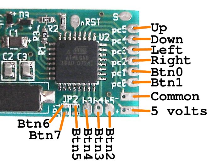
|
NeoGeo adapter wiring
Neo Geo controllers uses standard DB15 connectors. This connector is also used by old PC Joysticks but it incompatible. Here's a table describing how to wire a Neo Geo controller connector to this circuit:| DB15 pin | Neo Geo name | USB Game12 name | Comments |
|---|---|---|---|
| 1 | Common | Common | |
| 3 | Select | Button 5 | |
| 4 | D Button | Button 3 | |
| 5 | B Button | Button 1 | |
| 6 | Right | Right | |
| 7 | Down | Down | |
| 8 | +5v | +5v | Only for some controllers |
| 9 | D Button | Button 3 | Duplicates pin 4 |
| 11 | Start | Button 4 | |
| 12 | C button | Button 2 | |
| 13 | A button | Button 0 | |
| 14 | Left | Left | |
| 15 | Up | Up |
Disclaimer
I cannot be held responsible for any damages that could occur to you or your equipment while following the procedures present on this page. Also, I GIVE ABSOLUTELY NO WARRANTY on the correctness and usability of the informations on this page. Please note, however, that the procedures above have worked in my case without any damages or problems.Now you cannot say that I did not warn you :)