SNES to PSX: SNES controller to Playstation adapter
Project overview
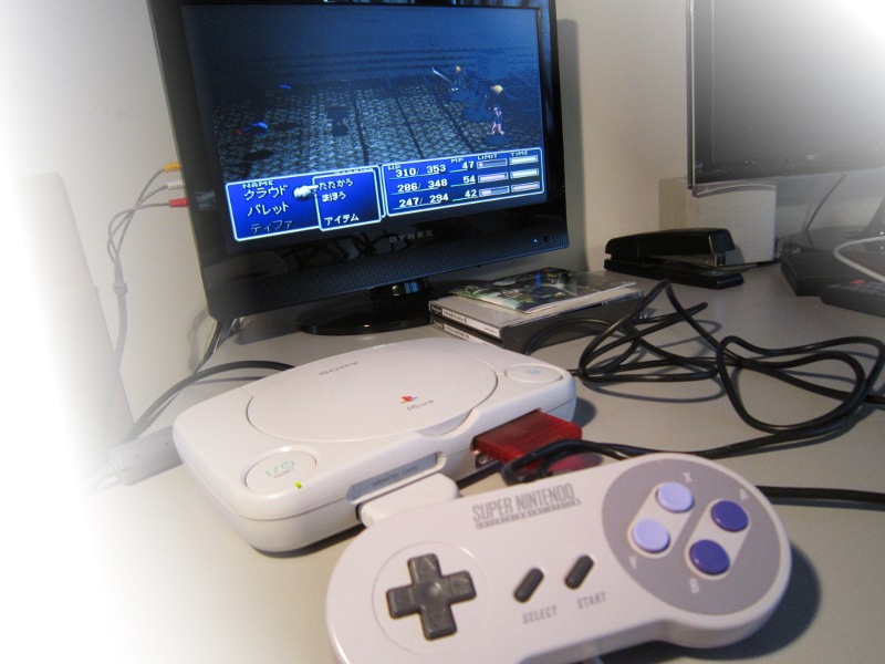
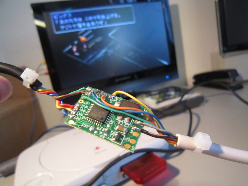
FF7 using an SNES controller
In fact, a few years before (2007), I had made the same project for another person. It's just that somehow, I forgot to publish it. So all I had to do was some code clean up and adapt the wiring for my modern multiuse PCB.
Specifications:
- Supports original SNES controllers and most clones.
- Acts like an original Playstation digital controller. Not usable for games requiring an analog controller.
- Two button mappings are available and selected by holding down buttons when connecting the adapter or turning the console on.
Mappings
| Mappings | |||||||
|---|---|---|---|---|---|---|---|
| SNES button | Type 1 | Type 2 | Type 3 | Type 4 | Type 5 | Type 6 | Type 7 |
| B | X | O | Triangle | Square | O | X | X |
| Y | Square | X | O | X | Triangle | Square | Square |
| A | O | R2 | X | Triangle | Square | O | O |
| X | Triangle | Triangle | Square | O | X | Triangle | Triangle |
| R | R1 | R1 | R1 | R1 | L1 | R2 | L1 |
| L | L1 | Square | L1 | L1 | R1 | L2 | R1 |
| Start | Start | ||||||
| Select | Select | ||||||
| Up | Up | Down | |||||
| Down | Down | Up | |||||
| Left | Left | Right | |||||
| Right | Right | Left | |||||
Mapping selection:
| Mapping | Instructions | Comments |
|---|---|---|
| Type 1 | Default mapping. | Natural layout of SNES XYAB to PSX ☓○△□ |
| Type 2 | Hold SELECT at power-up | Formerly known as the "Quang" mapping. |
| Type 3 | Hold A at power-up | |
| Type 4 | Hold B at power-up | |
| Type 5 | Hold X at power-up | Another variation. R1/L1 swapped. |
| Type 6 | Hold Y at power-up | Same as Type 1 with R2/L2 instead of R1/L1. |
| Type 7 | Hold L at power-up | Directions reversed for right-hand steering on arcade sticks. |
Games tested
Digital controller
Tested working PS1 games as of version 1.2:
Arcade Party Pak, Captain Commando, Chrono Cross (US), CoolBoarders 4 (US), Don Pachi & Do Don Pachi, Ehrgeiz (JP), Einhänder, Final Fantasy Anthology: FFV (US), Final Fantasy Anthology: FFVI (US), Final Fantasy Chronicles: FFIV (US), Final Fantasy Chronicles: Chrono Trigger (US), Final Fantasy Origins (US), Final Fantasy Tactics (US), Final Fantasy VII (JP)(US), Final Fantasy VIII (US), Final Fantaxy IX (US), Gradius Gaiden (JP), Gran Turismo 2 (US), グレイトヒッツ (JP), Harry Potter (US), Hebereke Popoitto, King of Fighters 99, Konami Arcade Classics, Legacy of Kain: Soul Reaver (US), Mega Man (X4, X5, X6, 8), Namco Arcade Museum Volume 1, Namco Arcade Museum Volume 3, Metal Slug, It might be NES, No Fear Downhill Mountain Bike Racing (US), Parasite Eve (US), PS1 menu (US), Puyo Puyo Sun, Puzzle Bobble (whole series), Rollcage (US), R-Type Delta Secret of mana, Smurf Racer! (US), Soulblade, Street Fighter (10 different ones), Tales of Phantasia (JP), Tekken 2, Tomba, Vagrant Story (US), Wild Arms 2 (US),
(Of course, many other games will work. Please let me know).
Non-working PS1 games:
With the current firmware (v1.2), there are no known non-working games.
With the previous firmware (v1.1), the following games did not work:
Ehrgeiz (JP), Einhander (JP), Rockman X3 (JP), Rollcage (US), Silhouette Mirage (JP), Tales of Phantasia (JP), Tobal 2 (JP), Vagrant Story (US),
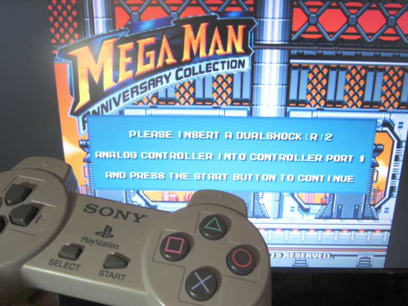
PS2 games:
Even though the PS2 menu does work, most PS2 games seem to require an analog controller to be present, even when they work perfectly without. Notably: Mega man anniversary collection does not work.
Ok... and the reason is?
Schematic and wiring
First of all, the schematic: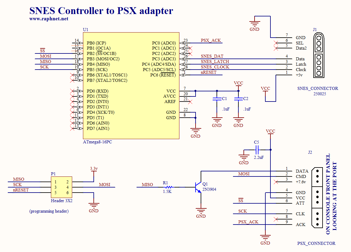
Here are a few notes about the signals:
| Playstation | |||
|---|---|---|---|
| # | Name | Location | Comments |
| 1 | DATA | PB4 | Through transistor (Open-collector output). SPI MISO. (to PSX) |
| 2 | CMD | PB3 | SPI MOSI (from PSX) |
| 3 | +7.6V | Not used | |
| 4 | GND | GND | Power supply (from PSX). |
| 5 | +3.3V | VCC | Power supply (from PSX). |
| 6 | ATT | PB2 | SPI "Chip select" (from PSX) |
| 7 | CLK | PB5 | SPI SCK (from PSX) |
| 8 | N/A | ||
| 9 | ACK | PC0 | "Simulated" open collector (to PSX) |
| SNES | ||
|---|---|---|
| Nom | Location | Comments |
| Clock | PC5 | |
| Latch | PC4 | |
| Data | PC3 | |
| Vcc | VCC | +3.3 volt |
| Gnd | GND | |
Notes:
- "Open collector output": An output connected to a collector (or drain) only. Such an output can "pull" a signal to 0 (logic low) but cannot "push" it to 1 (but a resistor somewhere does). The AVR SPI output (MISO for Master In Slave Out) is of the push-pull type so I am using an external transistor. Connecting the MISO pin directly would result in a conflict with the corresponding memory card slot which shares the same signals.
- "Simulated open collector": A technique where a GPIO is toggled between "output, low" mode and "input" mode.
- Clock: This design uses the AVR internal RC oscillator. No crystal required.
- Normally, SNES controllers run at 5 volt, but I know by experience that SNES controllers also work at 3.3v quite well. Doing so means the circuit can be simplified by using the 3.3v from the Playstation directly (instead of using a regulator).
Software
| Version v1.3 June 29, 2014 (Sunday) |
|---|
| Add 5 new button mappings |
| File(s): snes2ps-1.3.tar.gz (15.9 KB) snes2ps-1.3.hex (2.7 KB) |
Show previous releases...
| Version v1.2 June 1, 2014 (Sunday) |
|---|
| Improved game compatibility |
| File(s): snes2ps-1.2.tar.gz (15.6 KB) snes2ps-1.2.hex (1.8 KB) |
| Version v1.1 March 1, 2014 (Saturday) |
|---|
Initial public release:
|
| File(s): snes2ps-1.1.tar.gz (15.3 KB) snes2ps-1.1.hex (1.8 KB) |
 This project is also available on GitHub!
To request features, report issues or contribute, you may send me an email or use the GitHub repository:
https://github.com/raphnet/snes2ps
The Atmega8a has to be programmed using the .hex file. The "fuse bytes" for this project are high_byte=0xd9, low_byte=0xe4.
For more information about the tools required to program an AVR microcontroller, please visit my AVR programming page.
Source Code (.tar.gz files):
Unless indicated otherwise, the source code is published under the GPL license version 3. Please consult the included gpl.txt file for more information. The project compiles using the included makefiles using avr-gcc under Linux.
Pictures
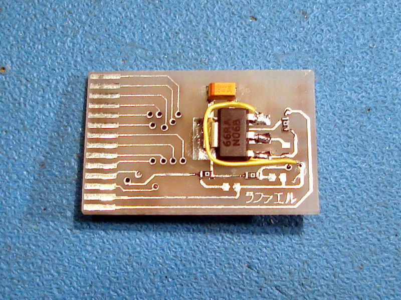
Here is the prototype I built in 2007. I had used my Multiuse tiny1 to build an adapter: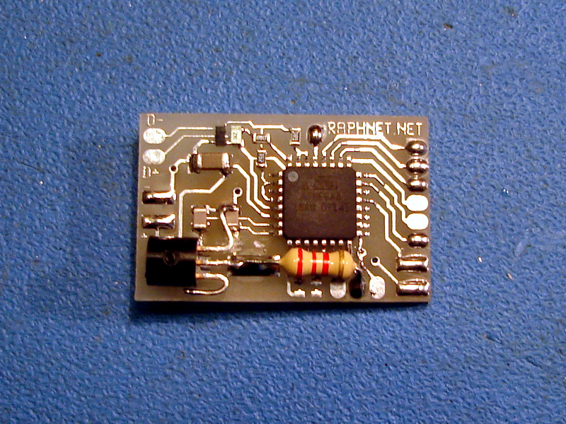
The adapters I now build (and sell in my store) are based on my Multiuse PCB2 circuit which has conveniently has a footprint for the required transistor on the bottom side.
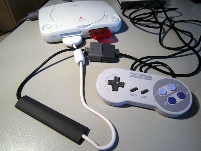
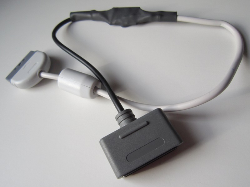
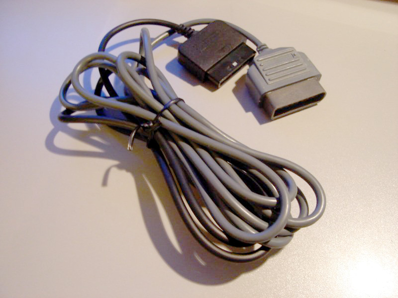
Warning: Do NOT rely on the wire colors shown in the above pictures. The relationship between pin numbers and wire color varies according to the cable manufacturer, and sometimes even between batches. You must find out the color code used by your cables using a continuity tester. Blindly following the colors seen here may damage your Playstation, your SNES controller and the adapter circuit.
Pictures from users
Seeing how others build my projects is always a pleasure. Send me your pictures and I'll add them here. Also let me know if you have a name/alias and country I can mention. By default, I will use your first name.References
A text file named Playstation.txt I downloaded a long time ago was most useful for this project.Disclaimer
I cannot be held responsible for any damages that could occur to you or your equipment while following the procedures present on this page. Also, I GIVE ABSOLUTELY NO WARRANTY on the correctness and usability of the informations on this page. Please note, however, that the procedures above have worked in my case without any damages or problems.Now you cannot say that I did not warn you :)