Leds and persistance of vision
Overview
There was an article named Glowstick a Go-Go in Make Magazine volume 1 which talks about a led bar which displays each line of an image one by one very quickly. If you move the led bar fast enough (left-right using your hand) you can see the picture like it's floating in the air.A few co-workers (see Etienne's blog at http://www.naid.net) and me thought that this was very cool so we decided to make some experimentation using the same concept.
Version 1
Fixed scan rate, no sync. Moved manually.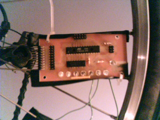
I used the PCB from an old project which had an Atmega8 MCU, an uln2003 and 7 high intensity red leds.
The MCU uses it's internal clock circuit. The 7 leds are controller by PORTD. To control the leds, I just write a value to PORTD and wait using a busyloop.
Here is the code (compiled with avr-gcc):
main1.c
Problems, solutions and possible improvements:
- The text starts displaying a any moment, regardless of your hand position. Adding an acceleration sensor could help synchronize the scanning with your hand.
- When you move the pcb from right to left, the text is reversed. A sensor should be added to detect the direction of the movement, and reverse the text when needed.
Version 2
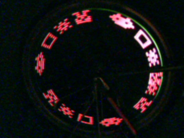
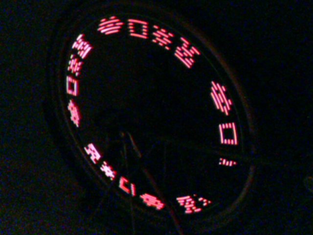
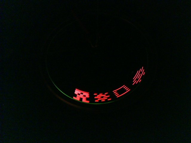
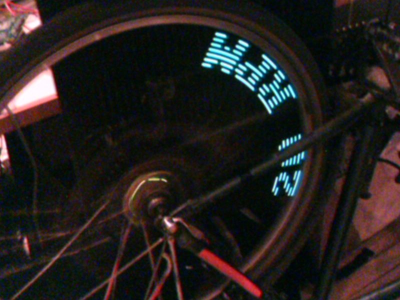
Fixed scan rate, no sync. Moved by a bicycle wheel.After we tried the first version of this experiment, a friend showed me a webpage with pictures of a stable image displayed on a bicycle wheel and text on a bicycle wheel, using the same technique as we do. We instantly decided to do the same thing. (Big thanks to Nic for the bicycle :))
No code changes were necessary for this, but I changed the text for a few old school low resolution videogames pictures.
Problems, solutions and possible improvements:
- The patterns start to be scanned at any moment regardless of the wheel position. The side effect of this is that it never appears at the same place (with the exception of the case where the time to scan the patern equals the time it takes for the wheel to do a 360 degree rotation). A position sensor is needed. I have fixed this in version 2.1.
- The pattern shrinks and grows depending on the speed of the wheel. We should calculate the wheel speed and adjust the scan rate accordingly.
Version 2.1
Fixed scan rate, synchronised. Moved by a bicycle wheel. In order to display the pattern always at the same place, I added a position
sensor made from a relay coil, a magnet and an amplification circuit.
In order to display the pattern always at the same place, I added a position
sensor made from a relay coil, a magnet and an amplification circuit.The magnet is fixed on the bicycle frame and the coil is inside the wheel. Each time the magnet passes near the coil, a small voltage is generated by the coil. The amplification circuit boosts this voltage to an acceptable level for the MCU.
A small code change was required to make this work correctly. Now, the MCU waits for a pulse, scans the picture one time and wait for another pulse. The picture is now always displayed at the same place:
Problems, solutions and possible improvements:
- The position sensor circuitry is big and relatively complex. A hall effect sensor would be simpler. Solution: Order from digikey...
- The pattern shrinks and grows depending on the speed of the wheel. We should calculation the wheel speed and adjust the scan rate accordingly.
- If a very long pattern is used, once the wheel completes a rotation
if is possible that the end of the pattern overlaps with the beginning. We must
choose how many pixels we wish to display during a complete rotation and adjust
the scan rate upon the wheel speed. A few code improvements will be needed.

- The wheel is not spinning fast enough to obtain an apparently fixed image. Using more than one opposed led bars on the wheel would help. (Riding a bike at 100Km/h is not an option).

Version 2.2
Fixed scan rate, synchronised. Moved by a bicycle wheel.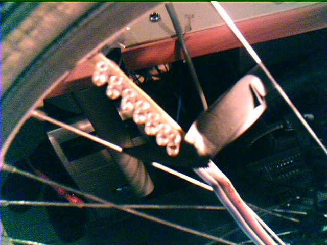 I replaced the on-board red leds by a few green leds installed on a strip of
perforated pcb. This has 2 advantages:
I replaced the on-board red leds by a few green leds installed on a strip of
perforated pcb. This has 2 advantages:- Improved visibility due to higher brightness
- The MCU board can be placed near to the center of the wheel resulting in a better balance.
I have also done some code improvements:
- The position sensor is now connected to an external interrupt pin.
- Every millisecond, a variable is incremented in a timer interrupt. When the position sensor interrupt occurs, the value of the millisecond counter is saved and the counter is reset to 0. This allows me to know how much time elapsed during the wheel's last revolution.
- A simple font has been added.
With the new code, it is possible to calculate the wheel's speed:
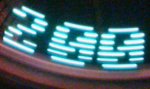
I had not enough time available to do it, but it will be easy to display the bicycle speed in Km/H instead...
Problems, solutions and possible improvements:
- Has the same problems as version 2.1
- Now that I know the wheel's speed, it will be possible to adjust the scan rate accordingly to obtain a display that does not stretch or shrink.
Version X
This is not a real version, it's just a place where we write down our ideas.MCU code ideas:
- Use an MCU timer to scan the pattern. Update the leds directly into the timer's interrupt routine (Output compate). The data for the leds is fetched from a buffer. One a scan completes, start over from the beginning.
- Route the sensor output to an external interrupt pin. In the interrupt routine, calculate the time since the last interrupt and adjust the scanning timer accordingly. Also force to scan from the beginning right away.
- To evaluate the time since the last pulse, another timer should be used to increment a global variable at a given interval.
- Implement scrolling text, speed display in the wheel :), dynamic animation depending on speed, special effects...
Hardware setup ideas:
- Use more than one opposing led bars in the wheel to obtain an apparently fixed display.
- Use more that 7 leds, to obtain a better resolution. When using more than 8 leds, more that 1 MCU port is needed. Will the delay between the first port update and the second cause a distortion?
- Try using different colors leds to make a color display.
- Try to light the leds with different intensities.
- Try doing this on a car wheel.
- Try doing this on a fan.
- Once a good display resolution is obtained, do a video game using this system as a display
Disclaimer
I cannot be held responsible for any damages that could occur to you or your equipment while following the procedures present on this page. Also, I GIVE ABSOLUTELY NO WARRANTY on the correctness and usability of the informations on this page. Please note, however, that the procedures above have worked in my case without any damages or problems.Now you cannot say that I did not warn you :)