Caller ID to PC
Overview
Some time ago, I subscribed to the Caller Id service to know who is calling me without being required to pick-up the phone. Unfortunately, my basic caller id display could not memorize enough numbers, and I had to write them manually in a computer to keep them. That's why I decided to find a way to log the calling numbers directly to my computer.After studying how caller id worked, I tried to buy a caller id decoding chip, but they all seemed to be discontinued. I bought another caller id module, expecting to find a suitable chip inside, but it was a single IC which did everything (Display, buttons, decoding).
Finally, someone gave me an old caller id module, and when I opened it, I discovered that it used a chip very was similar to the ones I wanted to buy :). The chip was different in that it required many external components to work, so I decided to leave it in the module, and to add the components I needed instead of building a complicated pcb. This has the side effect that the module still works as it always did, but with an additional feature: Serial data out.
Details
The caller id system in canada works like this:Between the first and seconds ring, the telco sends the modulated caller id data, at a speed of 1200 Bauds, 8N1. Once the data is demodulated, the caller id module interprets the data and displays the phone number and name.
There exists 2 standars to encode the data. SDMF (Simple Data Message Format) and MDMF (Multi Data Message Format). SDMF was the first standard used, and only supported the caller phone number and time. MDMF supports the phone number, name, time, locality(long distance or local)...
The modification
My caller id module uses the MT8843 demodulator. The demodulated serial data comes out of the pin number 17(data), at a rate of 1200 bauds, if the chip is in mode 0. The mode 0 is selected by connecting pin 9(mode) to ground. Fortunately, the caller id module worked this way. To send the data to the computer, all I had to do was to make sure the voltage levels are compatible. The TTL data coming out from the chip has to be converted to rs232 levels (+-12Volts). Also, it is important to isolate the computer from the phone line. I used an opto coupler to do this. Here's my schematic: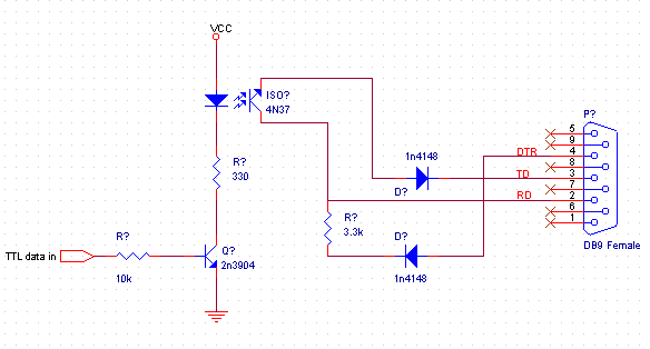
The signal coming from the MT8843 controls a NPN transistor (a 2n3904 on the schematic, but a 2n2222 would work too) which drives the opto coupler's led. This way, when the MT8843 signal is high, the opto led is on, which result in -12 volts on the RD signal. If the MT8843 signal is low, the opto led is off, and there is +12 volts on the RD signal.
As you may have noticed, the rs232 +12 and -12 voltages are coming from the computer. The idle state of the TD pin is -12 (the computer does not send anything so it stays at -12), and the DTR signal is kept at +12 volts by software.
Here is the site where I got some ideas to do the ttl/rs232 conversion: http://www.piclist.com/techref/io/serial/ttl-rs232.htm
Pictures
Here are a few pictures of the modification: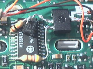
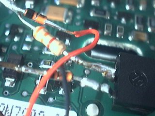
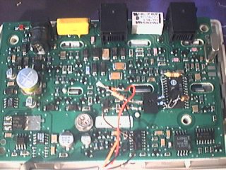
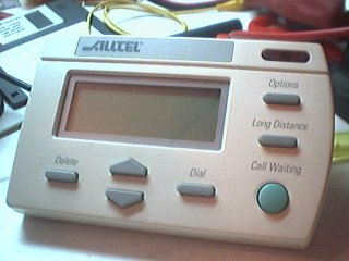
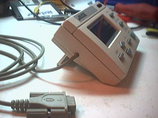
Note: After taking these pictures, I glued the components with a glue gun to make sure no short circuits occur.
Software
I wrote a software to log the incoming callers information. It is a simple daemon that runs under Linux. It is named cidlogd.Here is the source code:
cidlogd.tar.gz
Disclaimer
I cannot be held responsible for any damages that could occur to you or your equipment while following the procedures present on this page. Also, I GIVE ABSOLUTELY NO WARRANTY on the correctness and usability of the informations on this page. Please note, however, that the procedures above have worked in my case without any damages or problems.Now you cannot say that I did not warn you :)