APF TV Fun console repair
Overview of the system
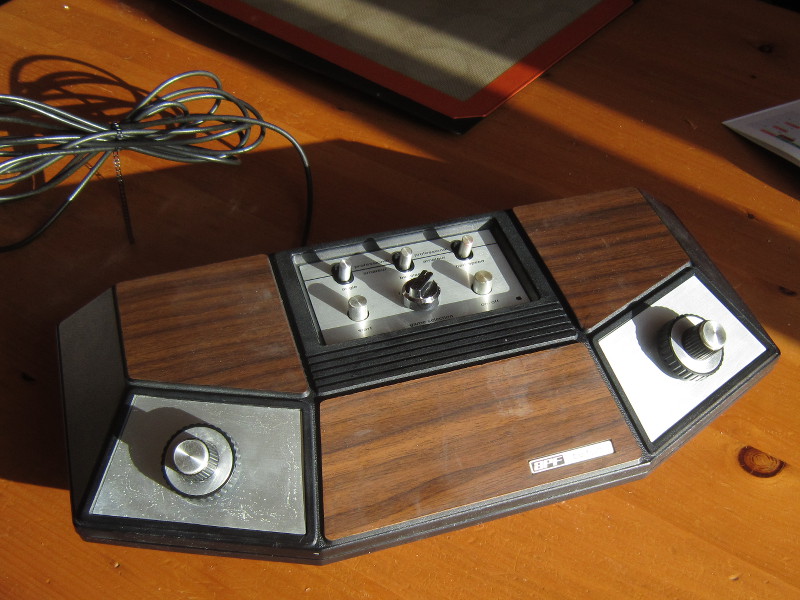
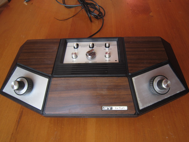
A friend entrusted me with the system described above (Model 401) for repairs. Here are a few pictures:
APF TV Fun
APF TV Fun
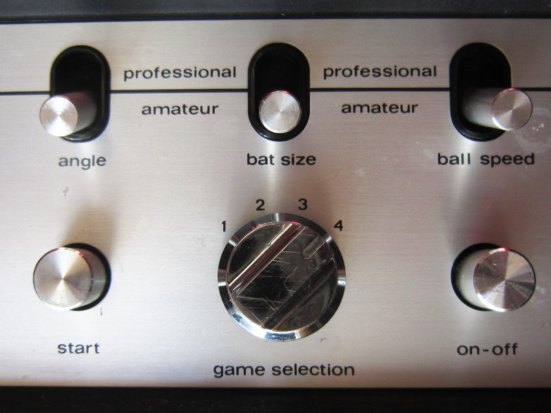
Game selection and options
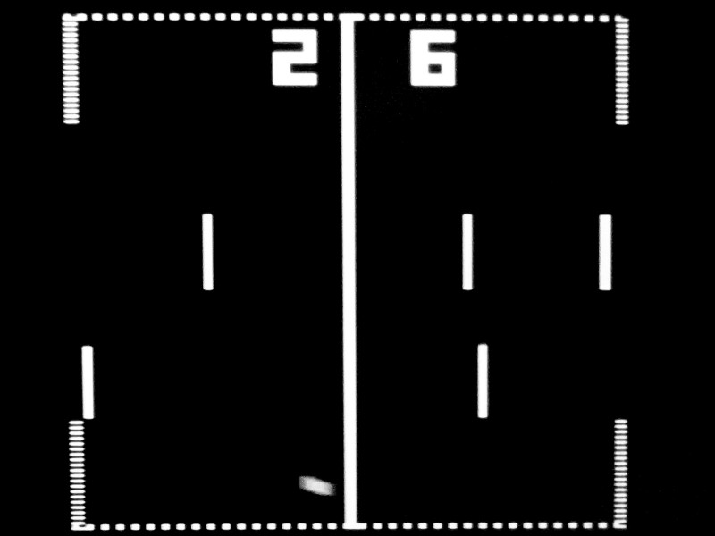
Here are screenshots for each of the four games:
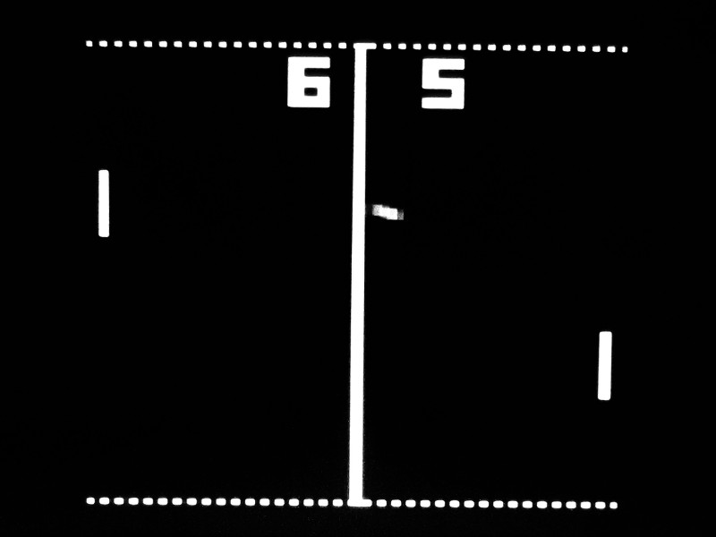
« Tennis »
« Soccer »
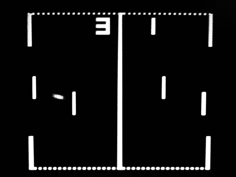
« Squash »
« Handball »
Despite being extremely simple, these games are still surprisingly enthralling! The controls have an instantaneous effect and are of a type perfectly adapted to the games. At the end of each match, doing a rematch to try to beat one's record (or adversary if you lost) is very tempting. It is not easy to stop playing. And if you ask me, it had better be that way. Given that according to old-computers.com this system sold for 125$ in 1976 and that this supposedly translates to about 513$ in 2014 dollars...
Undocumented game!
The Wikipedia page of the AY-3-8500 chip on which this system is based caught my attention:« In addition, a seventh undocumented game could be played when none of the previous six was selected: Handicap, a soccer variant where the player on the right has a third paddle. This game was implemented on very few systems. »
Undocumented game? Interesting. The AY-3-8500 has 6 pins dedicated to game selection. To enable a game, the corresponding pin must be connected to GND. It seems that if all 6 inputs are left floating, a seventh game is enabled: "Handicap soccer". It is a simply a variation of the hockey game shown above but where the right player controls three bats instead of two. Perfect when the two players are not of equal force.
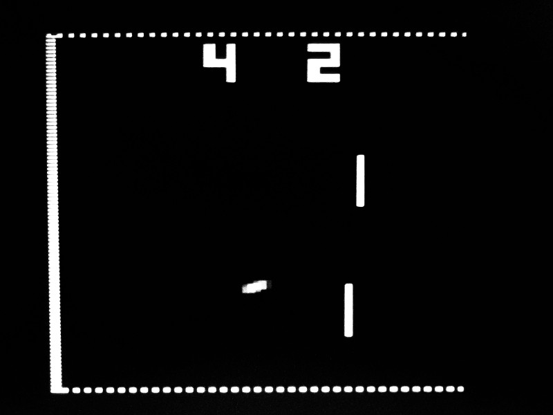
On the APF TV Fun, the undocumented game is active when the user sets the dial at the equilibrium point between any two positions:
« Regular soccer »
« Handicap soccer »
Examples:
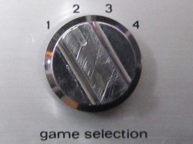
1-2
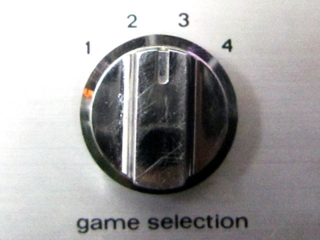
2-3
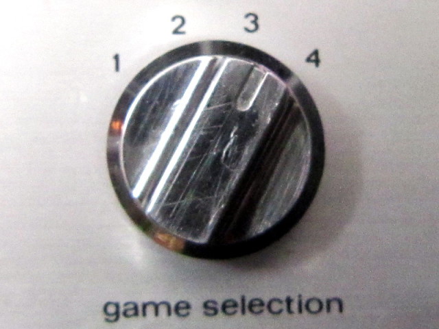
3-4
Problems
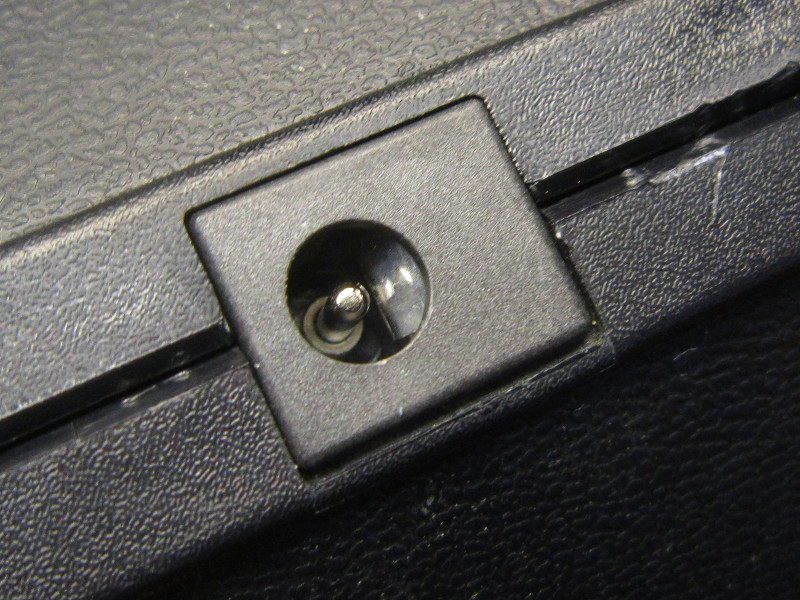
The console as I received it suffered mostly of cosmetic problems. Mostly, prolonged storage without removing the batteries beforehand was to blame. In short, the problems and solutions were:- One of the toggle switches stick was missing (broken at the base)
I could not find a replacement anywhere so I glued a replacement stick, machined from a piece of aluminium round. - Heavily contaminated battery contacts
I removed the old contacts and thoroughly cleaned the enclosure. I considered manufacturing new contacts, but in the end I simply gave up the possibility of using batteries. Now storing the system without removing the batteries will never happen again. - Contaminated power supply connector
Replaced it by a new part. - Contaminated video output connector.
Replacement of the old connector by a new part. - Control knobs too loose
Tightened the fastening nuts.
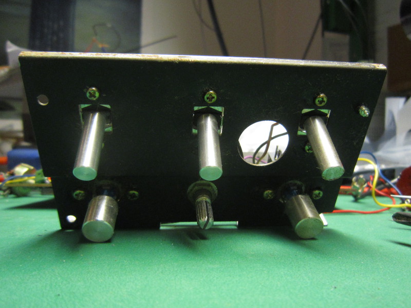
Inside
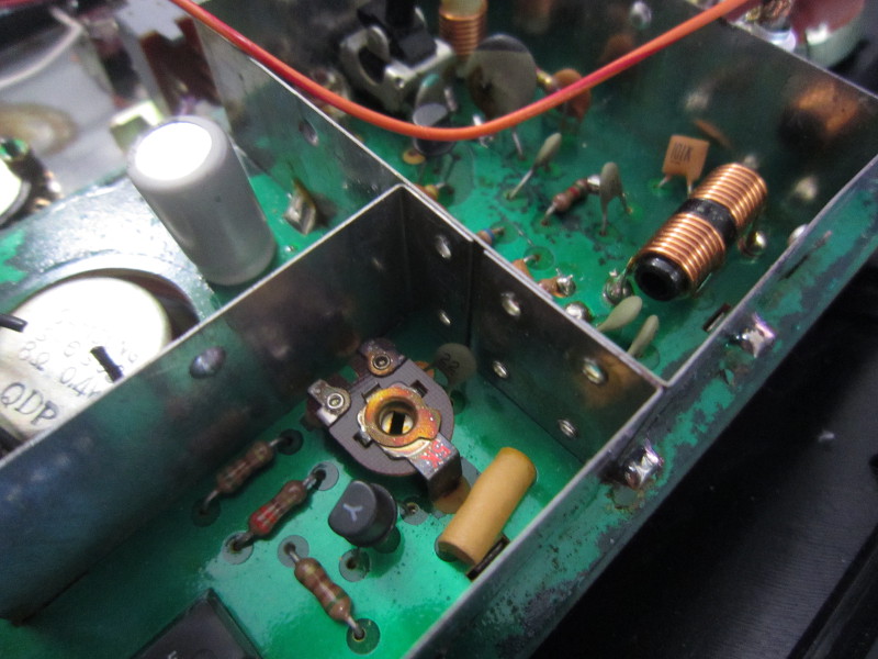
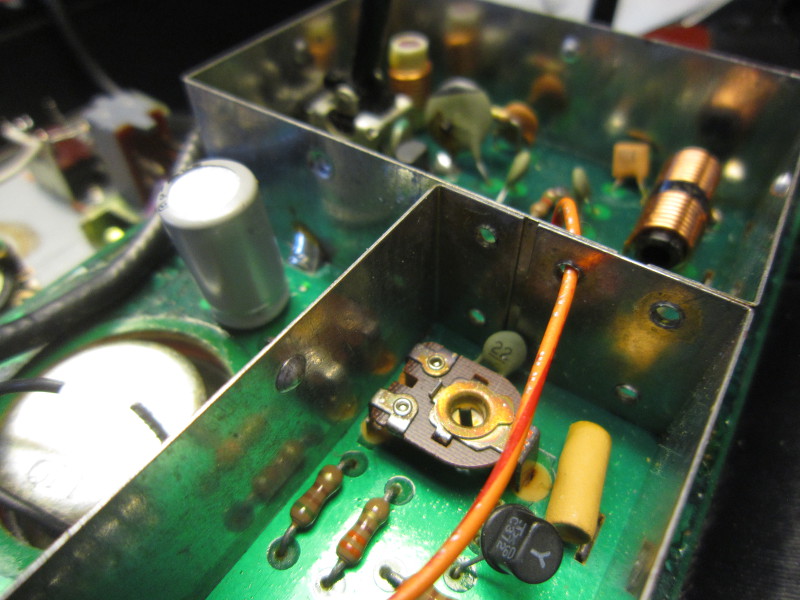
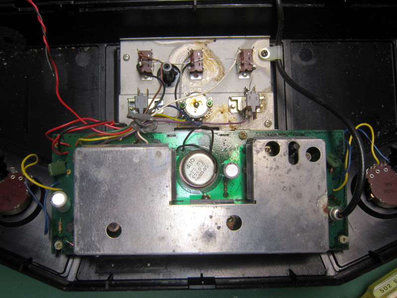
Now here are a few pictures of the internals: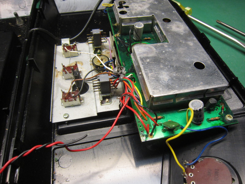
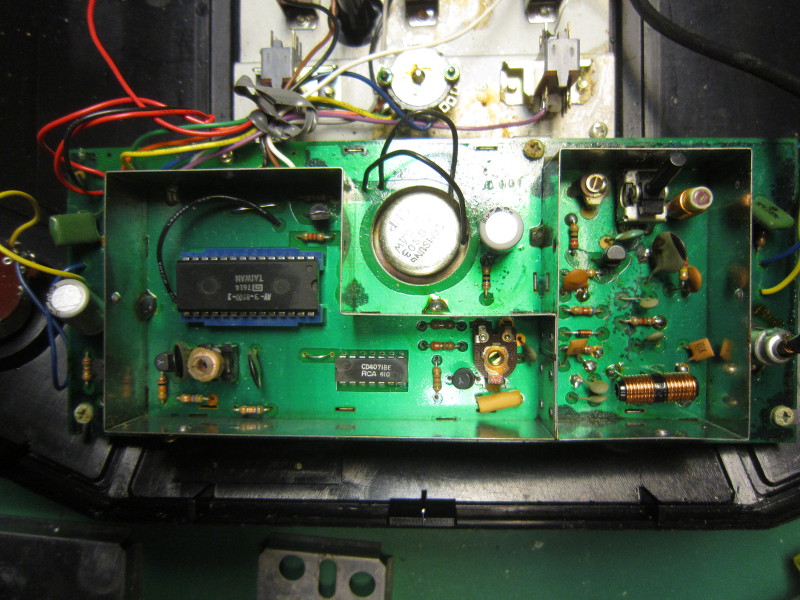
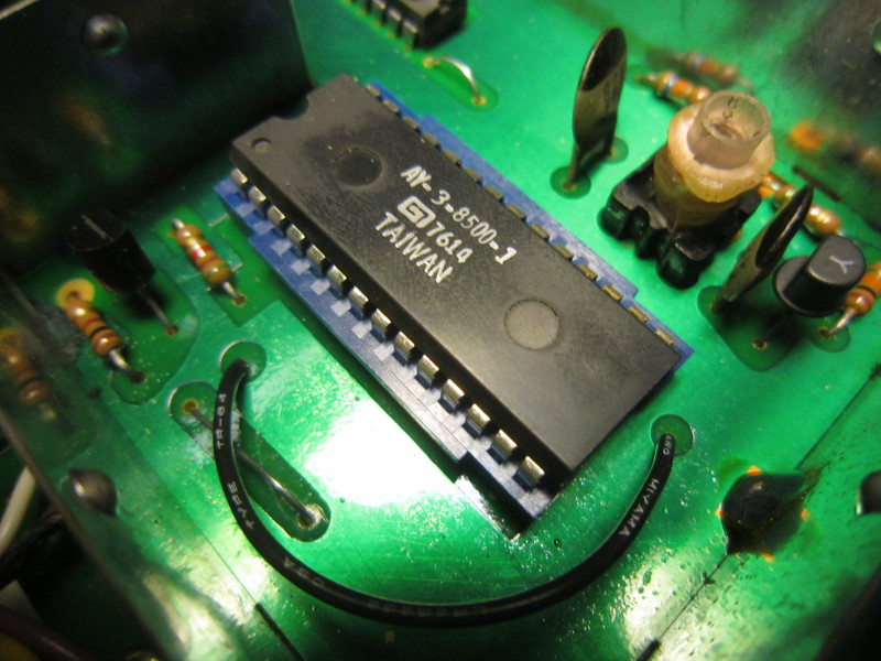
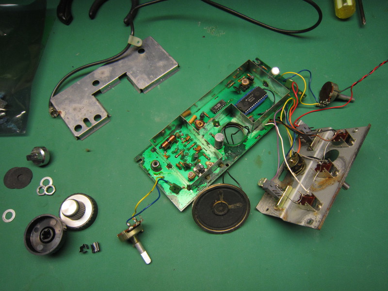
The circuit is very simply thanks to the use of the AY-3-8500 integrated circuit. By the way, here is the datasheet:
AY-3-8500.pdf
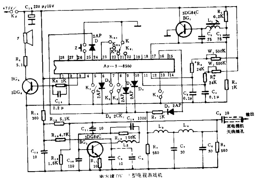
Using google images, it is possible to locate many different schematics of game consoles based on this chip. For reference, here is the most similar schematic I could find:
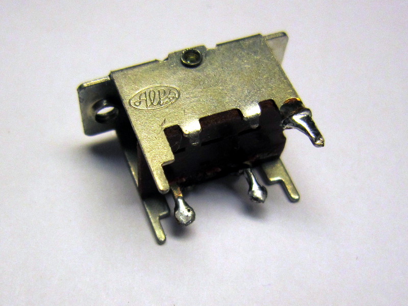
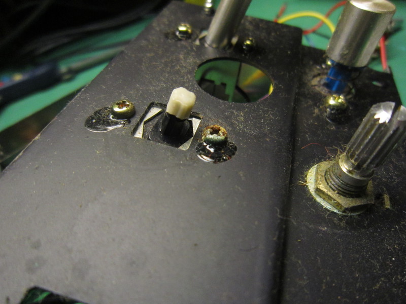
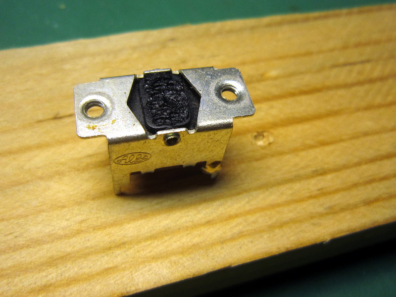
Replacement toggle switch stick
One of the toggle switches stick was missing (broken at the base) so I built a replacement which I glued in place.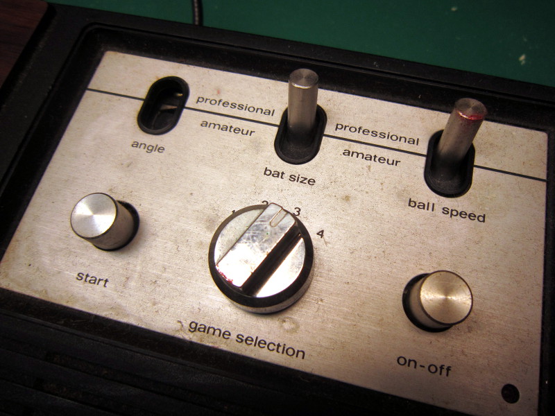
Missing stick
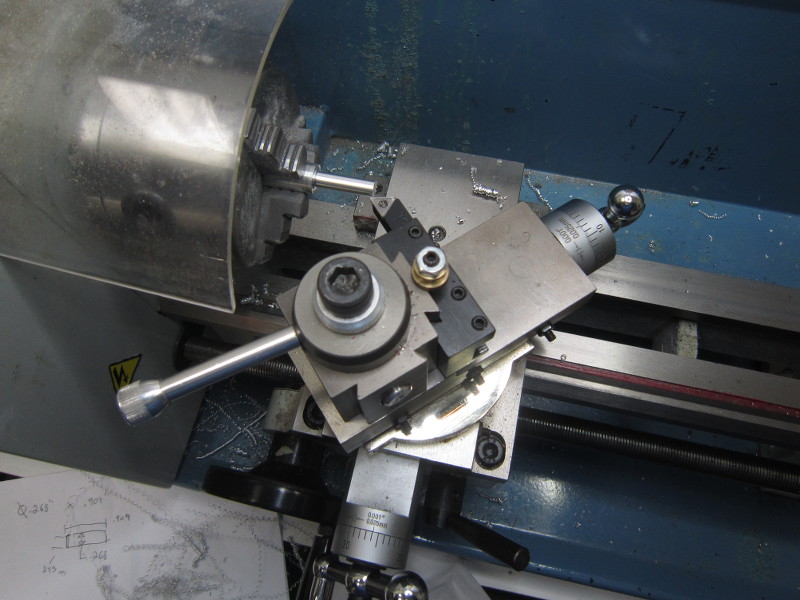
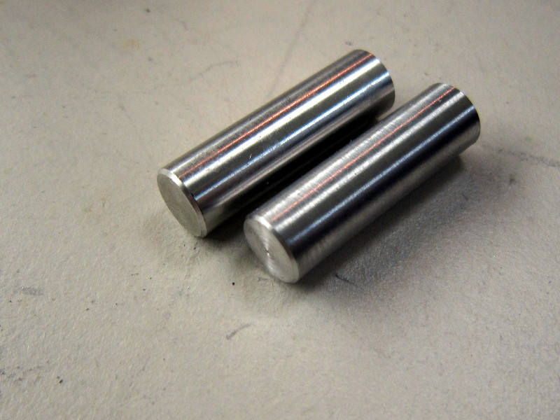
1. Turning the part
Using the stick from another switch as a model, I turned an aluminium piece until the same diameter was obtained. I cut a chamfer visually close enough to the original before cutting off the piece at its final length.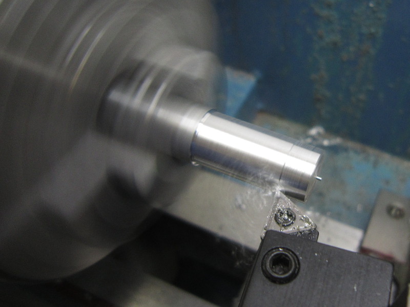
Diameter: Ok
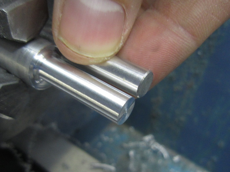
Length: Ok
Chamfer
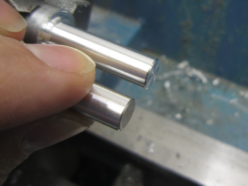
Chamfer: Very similar
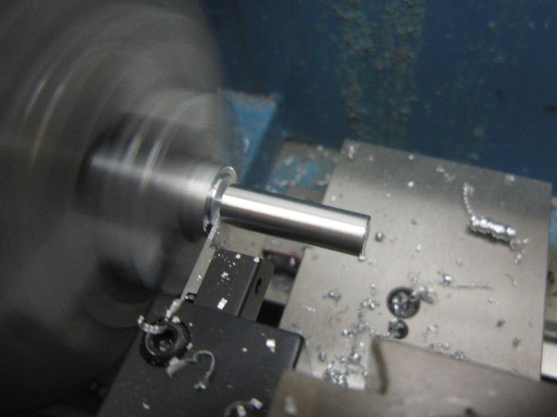
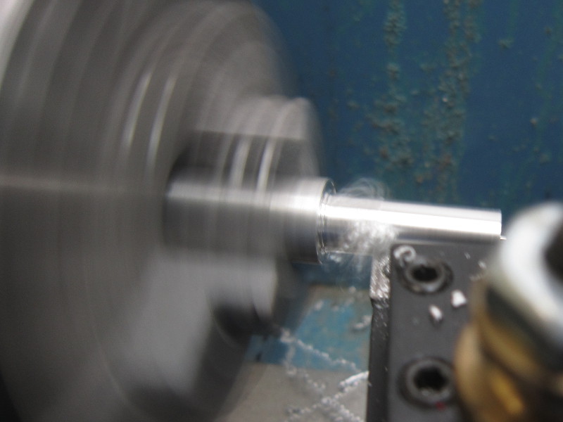
Cutting off
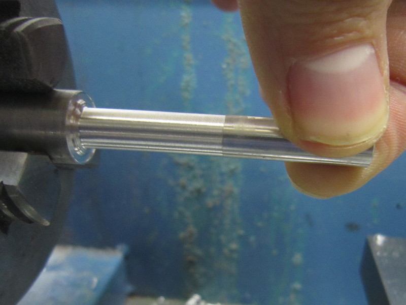
Result
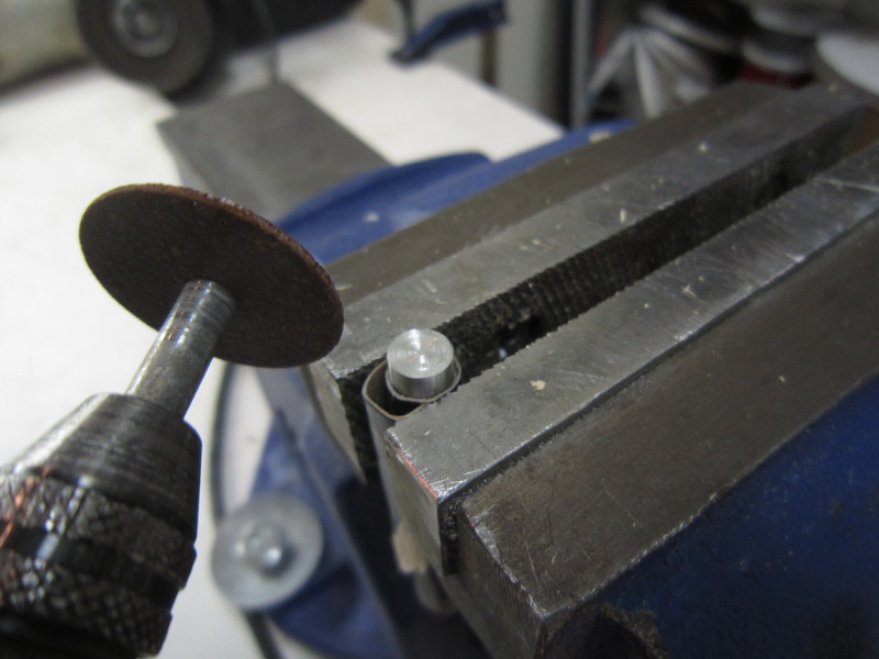
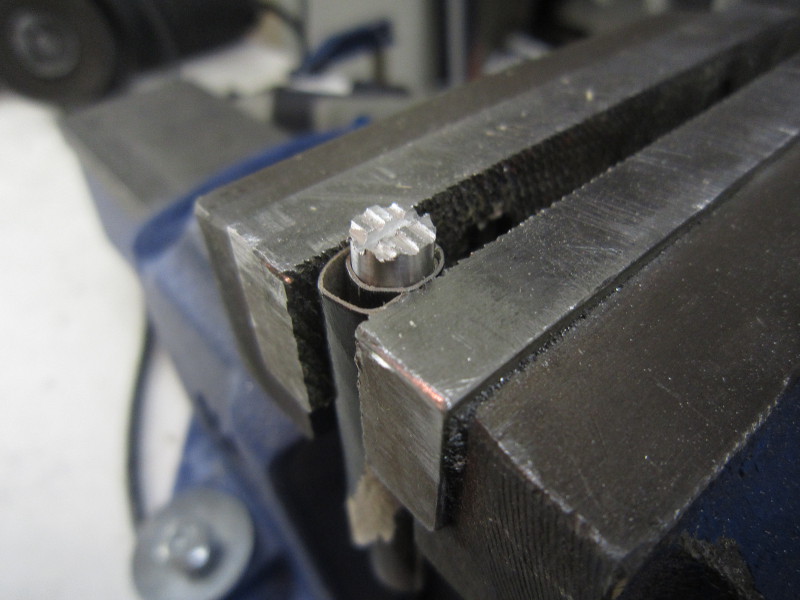
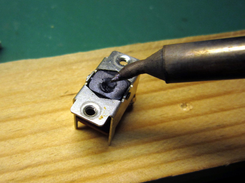
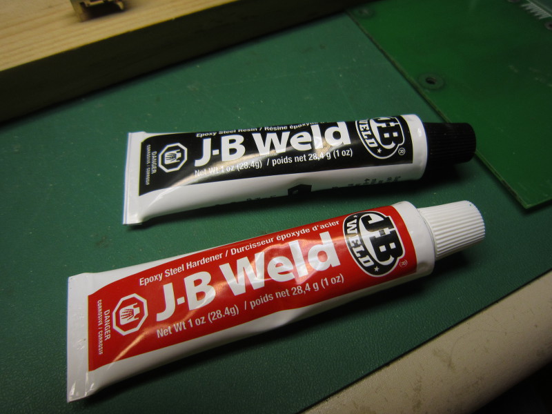
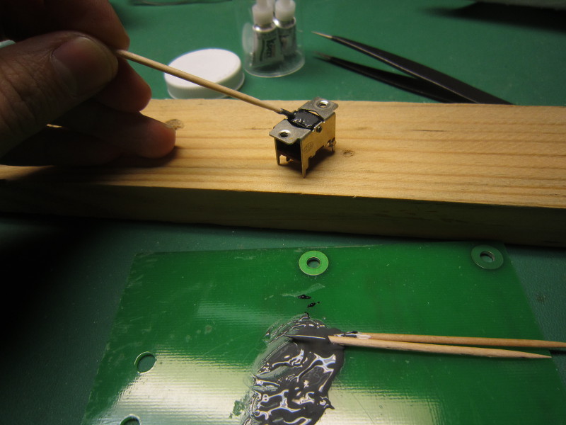
2. Preparations for gluing
Intending to use glue, I used a cut disc to give the base of the stick an irregular texture, in the hope of obtaining a stronger bond. For the same reason, on the switch side, I used the tip of my soldering iron to create a rougher surface.The adhesive I used is a type of epoxy.
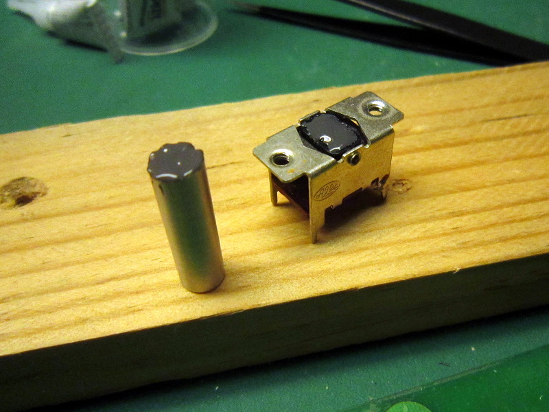
3. Result
24 hours later, the switch worked perfectly and did not look much different from the two others. The operation was a success.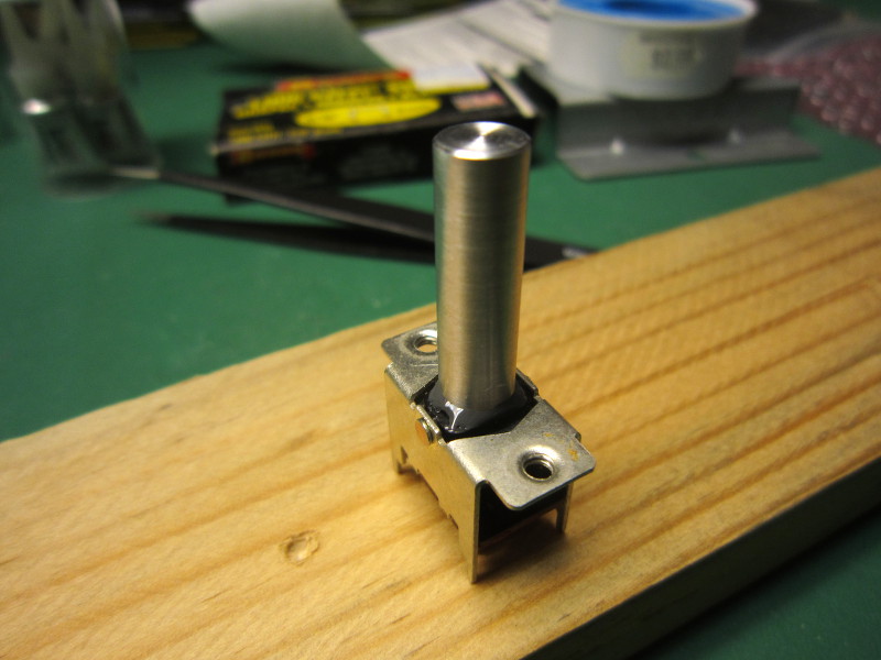
Power connector
The external power connector not having been spared by the leaking batteries, it was necessary to replace it. I expected I would have to machine an adapter part to hold the new connector in the original opening, but in the end I found a replacement with exactly the same dimensions!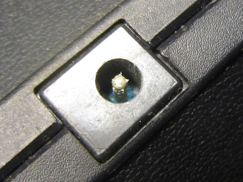
Verdigris in the power connector

Verdigris in the power connector
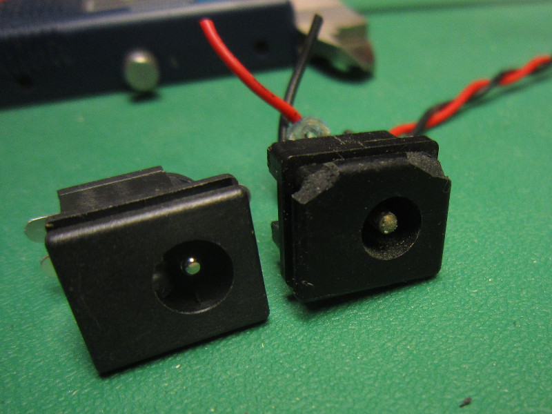
New vs. Old connector
Replaced connector
When running on 6 batteries, the total voltage was 9v. According to the datasheet, the maximum voltage rating for the AY-3-8500 chip is +12v. But the "standard" operating conditions are stated to be +6 to +7 volt, so I decided to use a 6 volt power supply. In any case, it will be more convenient than batteries.
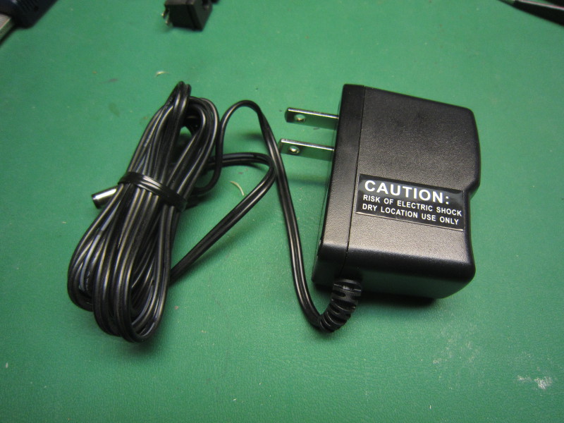
New power supply
Output connector
The RF output connector also had verdigris on it so I replaced it.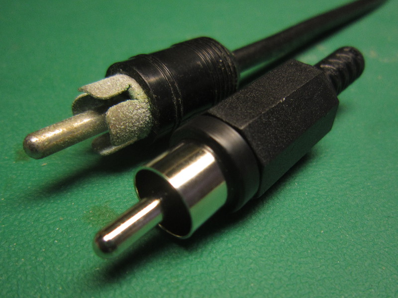
The old connector and its replacement
Battery compartment
Here's what often happens when you leave batteries in when storing a device. The batteries "leak" and surrounding metals are attacked. Look at those colorful crystals. It reminds me of coral reefs.
Heavy verdigris on battery contacts
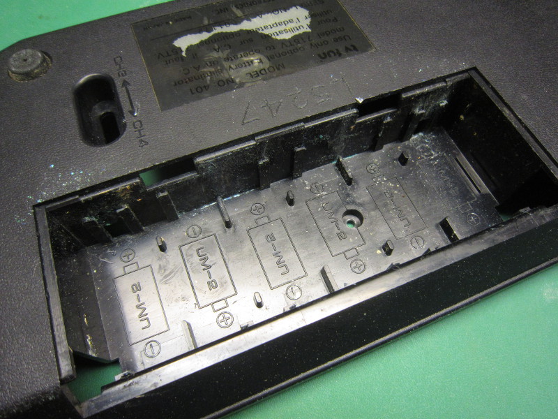
Contacts removed
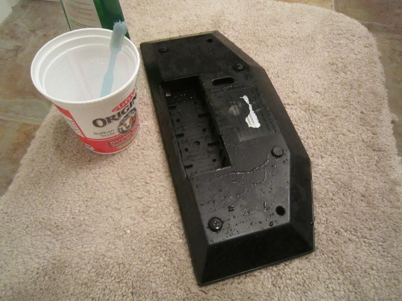
Cleaning up...
After removing the old contacts and cleaning the enclosure, I considered manufacturing new contacts, but in the end I simply gave up the possibility of using batteries. Now storing the system without removing the batteries will never happen again.
Composite-out mod.
In order to obtain a better image (less noisy) and make sure the system would be easy to use with modern an future tv sets, I converted the RF output to a composite output.The TV Fun combines all the video outputs from the chip (ball, paddles, score and obstacles) using a CD4071 and the resulting signal has its voltage lowered before going to the RF modulator. This is the perfect place to capture the composite video signal.
But the TV Fun circuitry is not designed to be connected directly to a TV Set. The impedance of a composite video input is 75 ohm, and the output impedance of TV Fun circuit is about 1000ohm (exact value depends on the adjustment). The resulting amplitude on the receiver side would be very low. (There was a picture when I tried, but it was very noisy and jumpy).
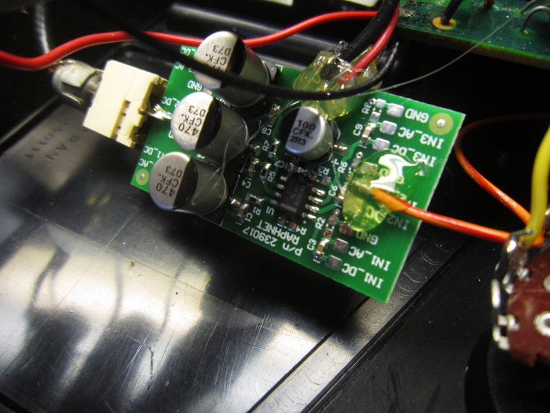
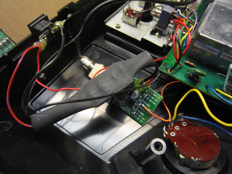
In order to send a strong signal to the TV, I built a simple video buffer (see my 3 Channel video buffer project) based on the THS7314 chip, a 3-channel operational amplifier with special features that help when dealing with video. Thanks to this circuit, the TV Fun electronics are isolated and spared the effort of driving a 75ohm transmission line. Modifications to the original circuitry are minimal, so undoing this mod would be easy.
The THS7314 IC works from 3 to 5 volt, but the console works at 6 volt so I had to use a regulator. I had one my my multiuse PCB2 assembled with a 3.3v regulator on hand, which I simply used.
Here are a few pictures of the modification. Note that the RF modulator is intact and still works.
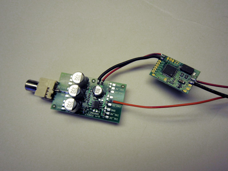
Video buffer and the regulator board
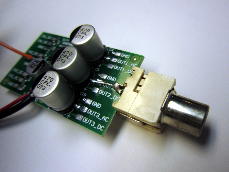
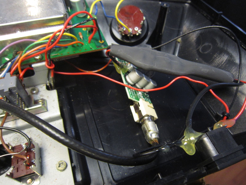
Video buffer
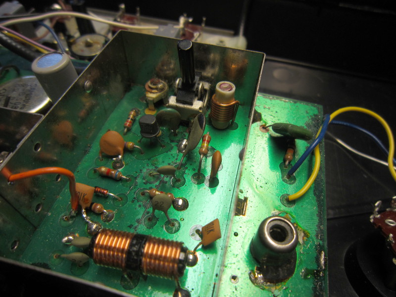
Capturing the video signal
Installation
A few additional pictures: