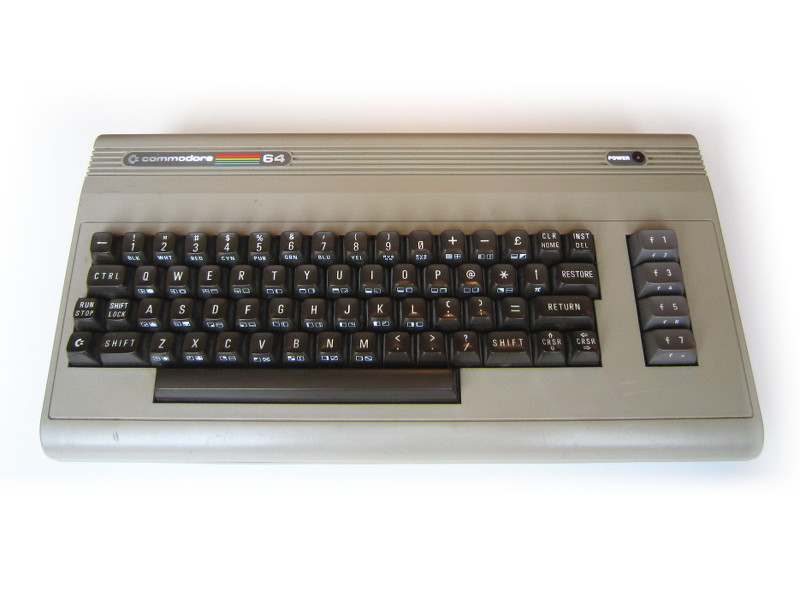
Commodore 64
Repairs first
Maybe I wanted to put my large format C64 schematic to good use (finally) or perhaps I was looking for a challenge. So I got a partial refund ("Working" auction converted to "As-is - untested") and impatiently began the repair.
1. A small soldering problem
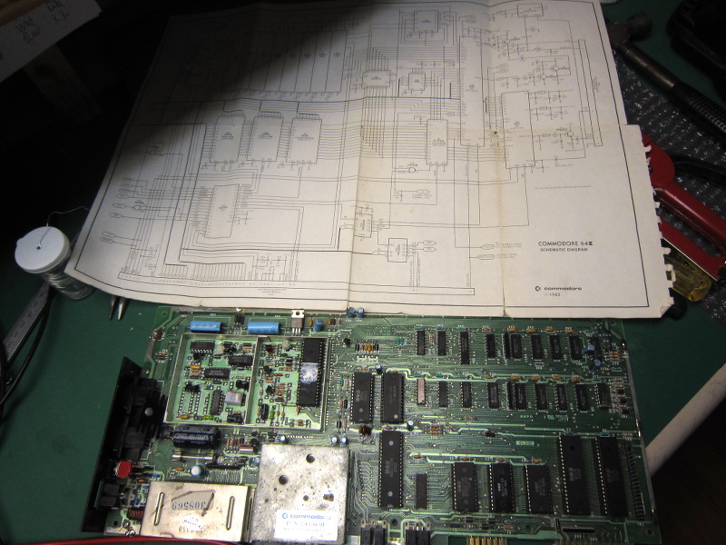
The board and its schematic
- Removal and reinsertion of all socketed chips. No change.
- Check for 5volt on the CPU, memory, and a few logic gates. No problem, nice clean 5v.
- Check if the CPU clock input has a signal. Yes.
- Check if the reset circuit work. Seems ok.
- Notice another 5 volt supply on-board (+5V CAN) obtained from the 9V AC input. I check it with a voltmeter: 0 volt. Ah ha! Finally a problem!
2. Replacing the RAM chips
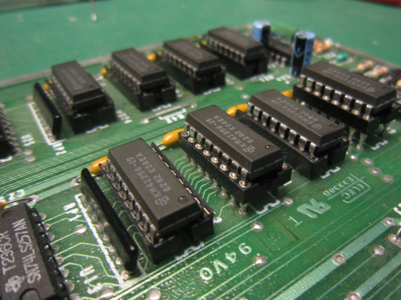
Replaced RAM chips
This time, I had a look to the CPU BUS and there was activity... I then somehow suspected the RAM might be in cause. In order to swap the chips with new ones (new many years ago), dis-soldering the chips and installing sockets is necessary. There are 8 DRAM chips so it took a while. I did it one chip at a time, testing the machine after each step. In order to quickly find the bad one(s), I did it from the dirtiest (the pins were black) to the cleanest, hoping I would find the bad one sooner. Well no luck, it only worked after the last chip was replaced. To remember: Never judge a DRAM chip by its appearance.
3. Black and white picture?
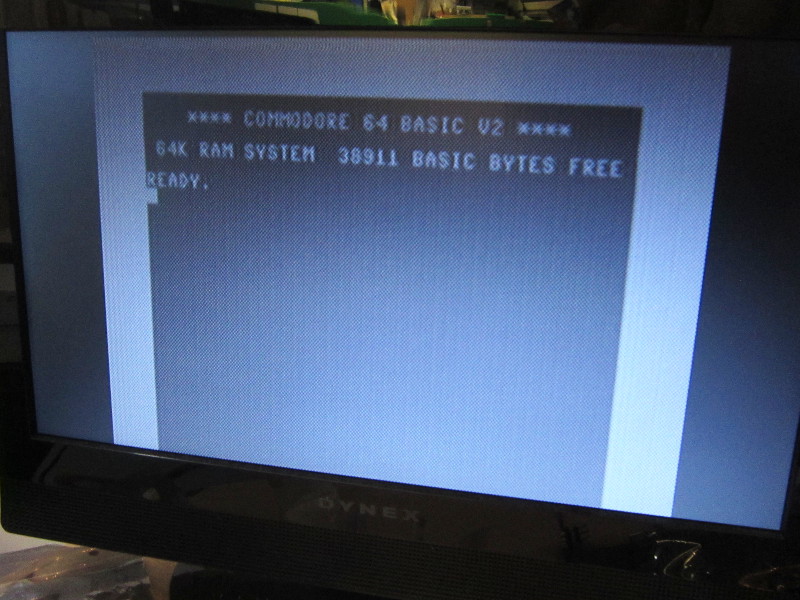
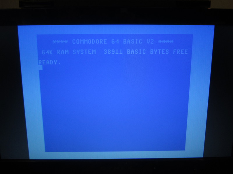
LCD: ...where are my colors!?
At that point I was using the RF modulator so I decided to try a composite connection instead. But it did not help. The result was a black screen with a "No signal" message. In short: RF = B&W + vsync problem, Composite = No picture.

CRT TV: Ok!
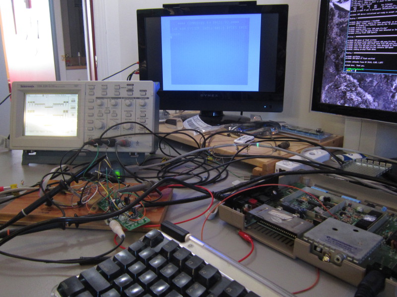
In the following section, the battle to convince my LCD monitor to accept and display the C64 composite video signal.
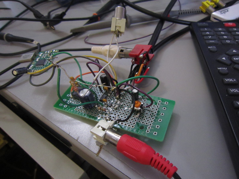
Composite video and and LCD TV
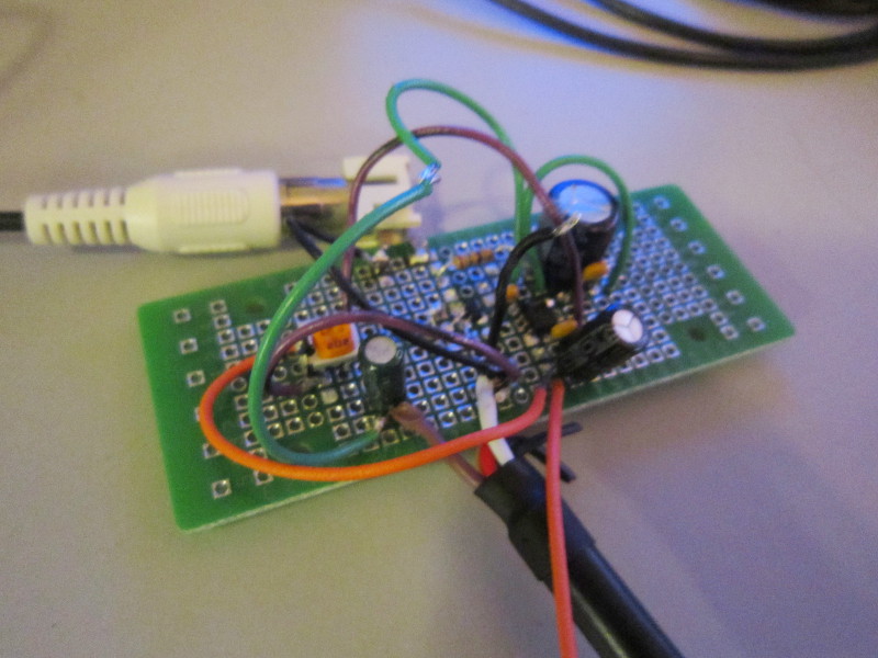
First circuit
With that in mind, I built a simple test circuit using a THS7314DR to obtain a 6db gain (you get 2V per volt). Now the output signal was strong. But still no picture on the LCD.
Without knowing exactly what could be wrong, I modified the circuit in many way to experiment various theories without success, until in an attempt to "trunc" the video signal from below to try and see if reducing the depth of the sync pulses would help. I did this by connecting the IC ground pin to a potentiometer.
Changing the sync depth did not work. However, by setting the potentiometer very carefully such that the sync pulses are almost completely gone, a nice picture suddenly appeared!
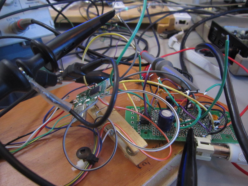
First working signal
Resulting picture

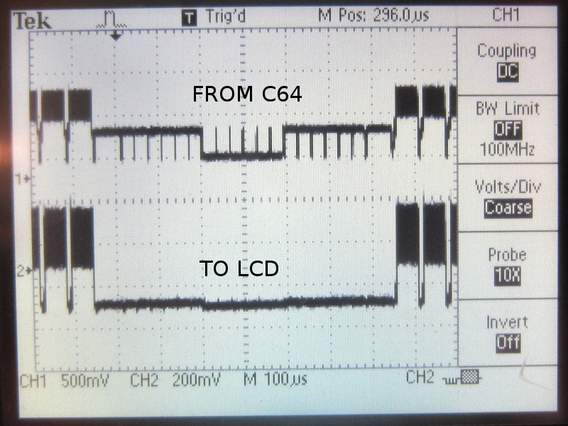
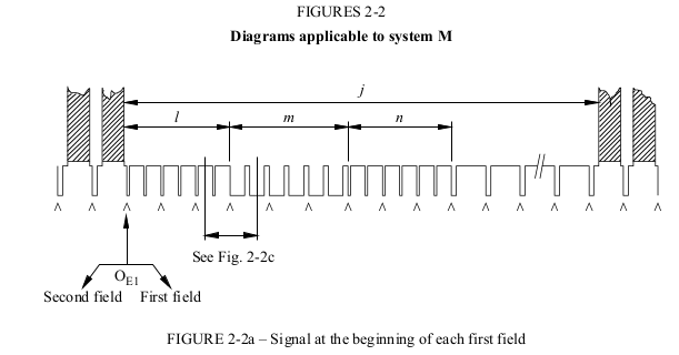
Signal from C64

Signal from C64
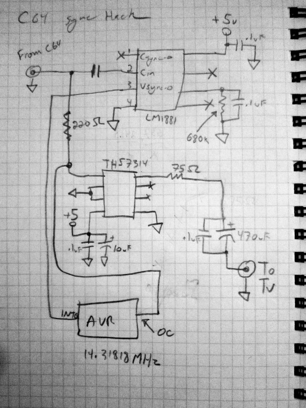
Sketch
My little experiment did yield a picture, but it was not an acceptable solution. The GND voltage had to be tweaked very precisely, and after a few minutes, it had to be fine tuned again (voltage drifting due to heating up, etc...).
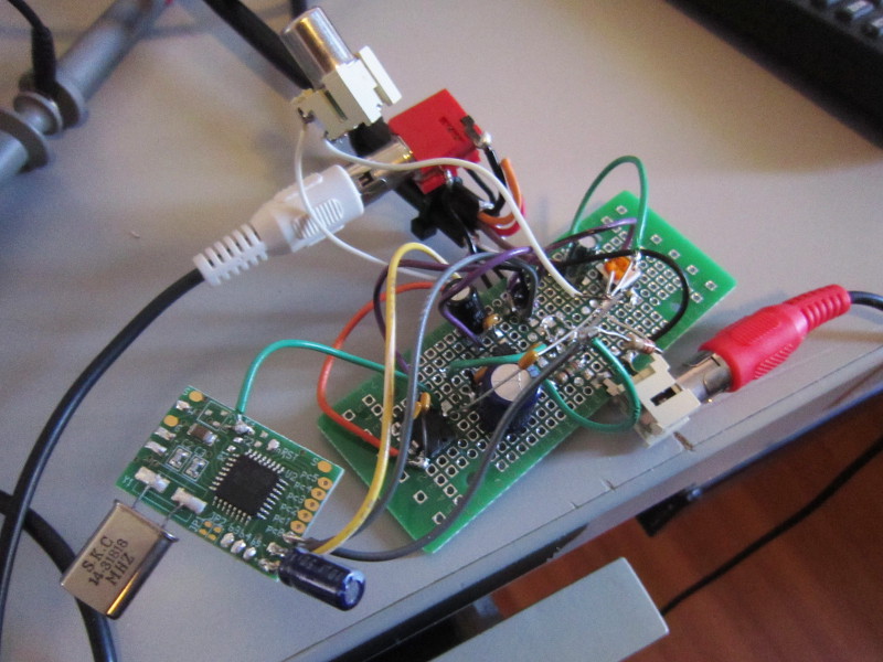
The next thing I did was to work on a better solution. I added an LM1881 sync separator to convert the sync pulses to a logic signal directly usable by a micro-controller. I also added an AVR micro-controller programmed to suppress the invalid sync pulse.
At first, the software only suppressed the small (approx 3us) incorrect pulse shown above. And just doing that was enough to get a picture on the LCD. However, I noted some horizontal jitter... After some experimentation, I found that completely suppressing the 'm' period worked well (the picture was stable), but it would probably be better to inject the correct pulses. I may do this eventually, but for now, it's working well!
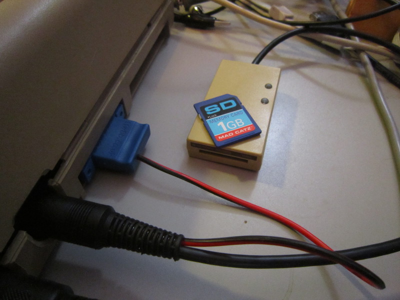
SD2IEC
I did not buy a disk drive for the computer, but it does not matter. There are now better solutions where the drive is replaced by an SD card!I considered buying an 1541Ultimate, an SD2IEC or a Chameleon64. I went with an SD2IEC for its availability, and also the price. I bought it here:
http://www.sd2iec.co.uk/id14.html
The SD2IEC has a disadvantage in that it does not support most fastloaders. Many games are available in cracked versions where the fastloader can be disabled, or with the fastloader removed. I'm told many demos are not available in no-fastloader versions so the SD2IEC would not be a good choice for demos.
Fortunately, SD2IEC supports, among a few others, the SJLoad fastloader which really reduces load time. Combined with CBM FileBrowser for navigating directories and disk images, it is really easy to use, and also not too slow. Some typing is required though: LOAD"!",8 and RUN followed by LOAD"FB",8 and then RUN again. ("!" is SJLoad and "FB" is the file browser. Manually-typed filenames are best when they are short).
SD2IEC
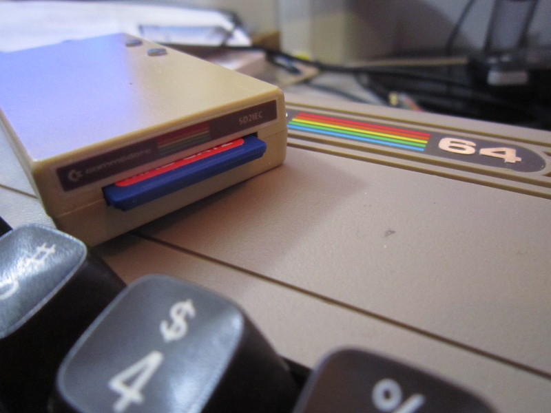
SD2IEC
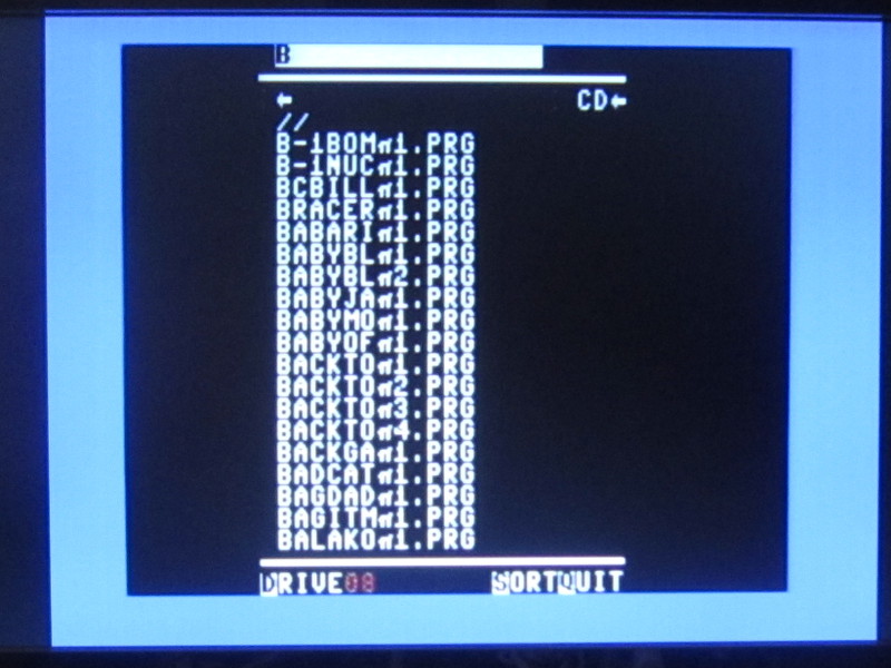
CBM FileBrowser
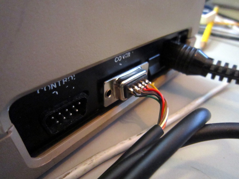
SNES controller
While I sometimes use my competition pro joystick, I tend to prefer SNES controllers because that's what I grew-up with. Using SNES controllers with on a Commodore 64 is possible with my SNES to Atari/Commodore adapter. In many games, the joystick-up direction is used to jump which is not comfortable on a gamepad. This is why my adapter has mappings (see Style 2 and 3) to map this direction to buttons.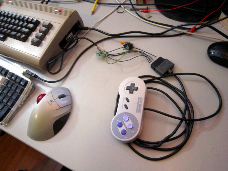
A few games
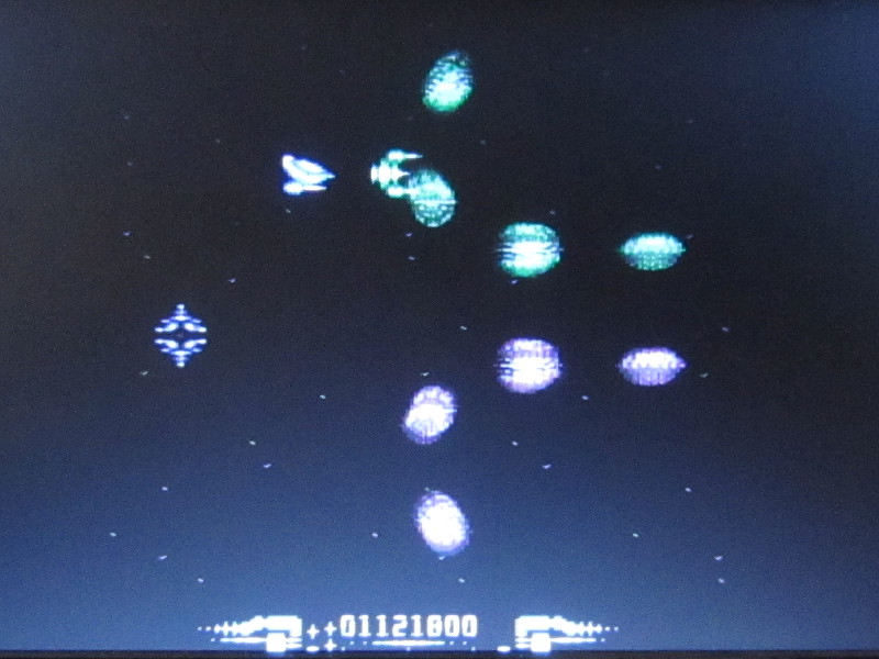
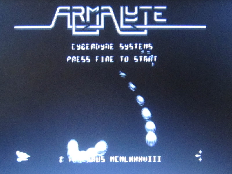
In conclusion, here are a few pictures of games I recently played.Armalyte
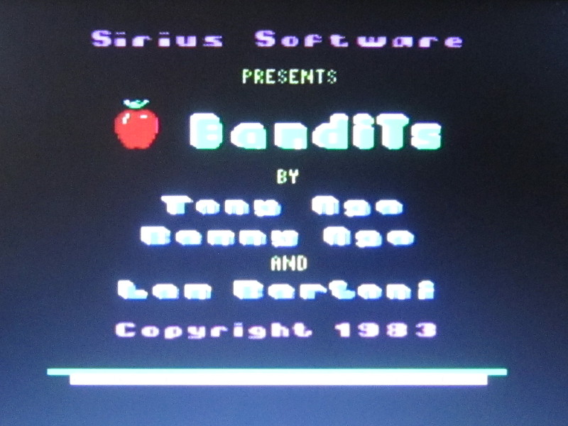
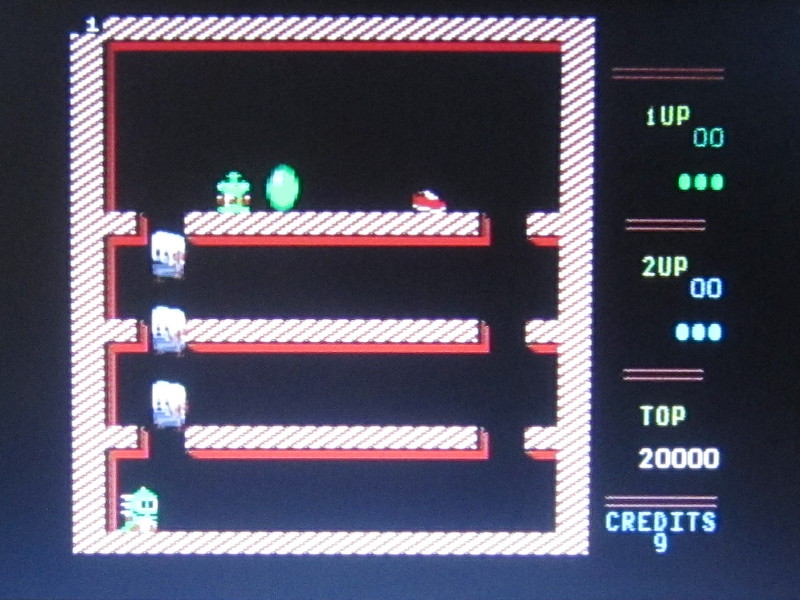
Bandits

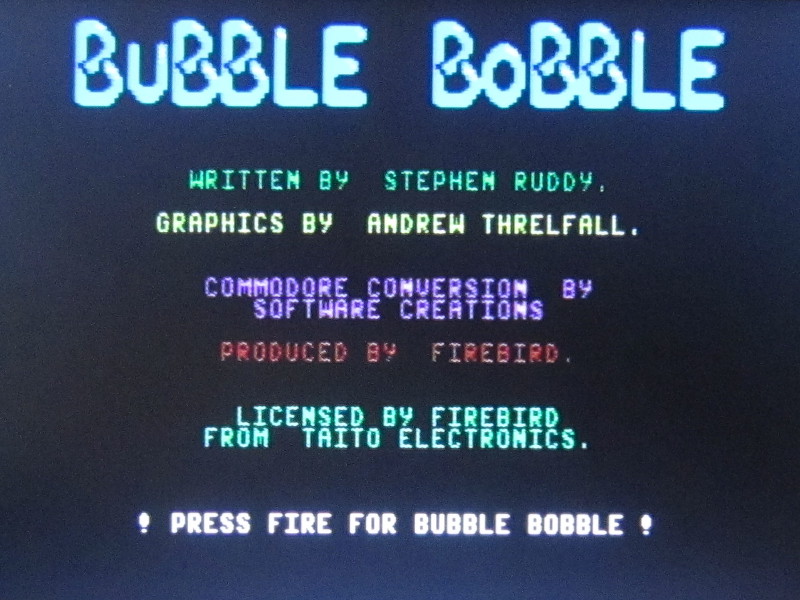
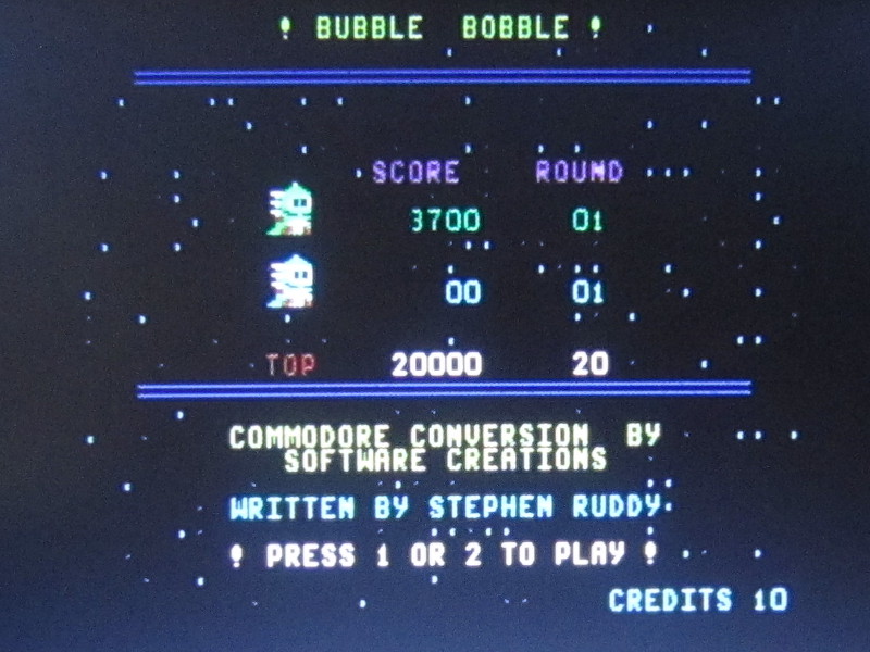
Bubble bobble
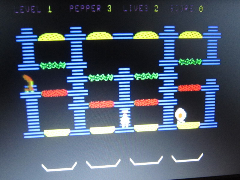
Burger time
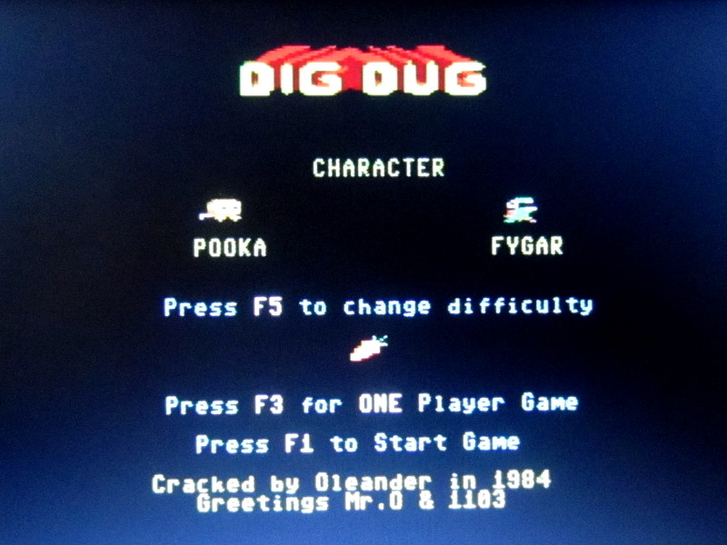
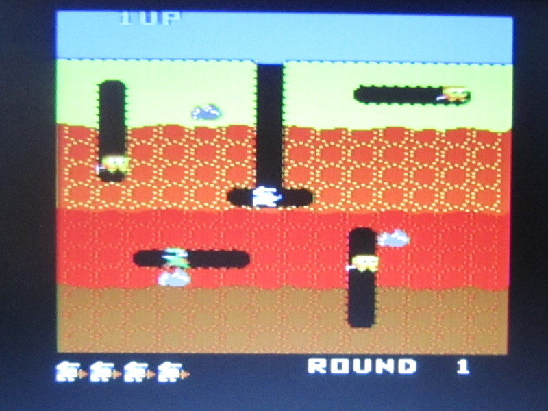
Dig Dug
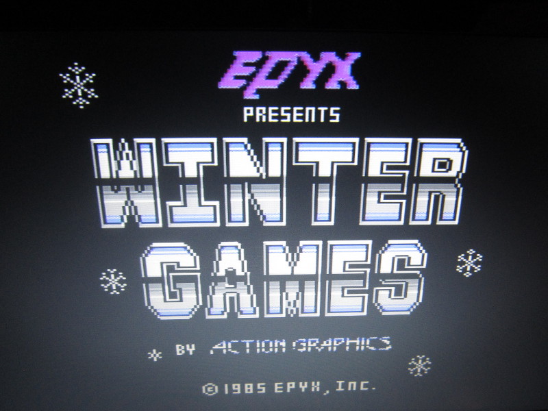
Winter Games

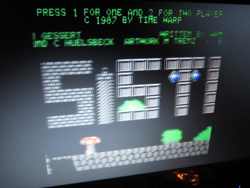
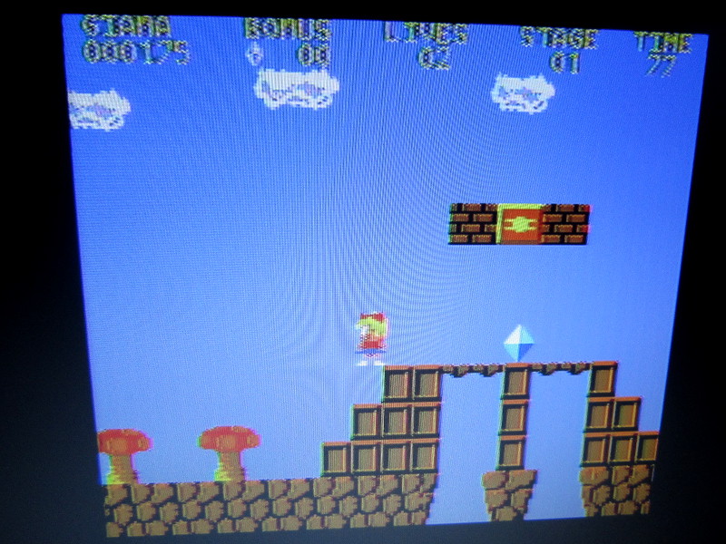
The great Giana Sisters