Acrylic SNES
Inspiration
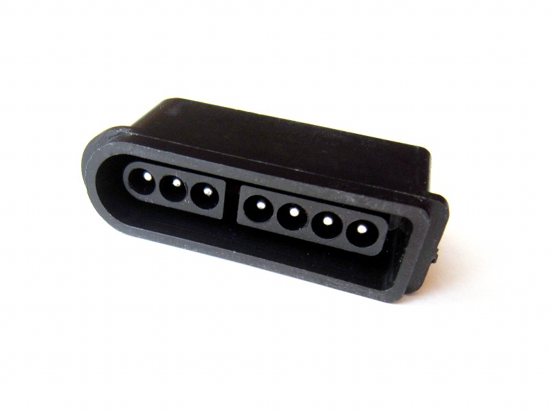
The SNES connector
 After finally finding a supplier for SNES style controller connectors,
I was considering doing an adapter in a machined aluminium enclosure,
as I had previously done for the NES. (See AnodeNES).
After finally finding a supplier for SNES style controller connectors,
I was considering doing an adapter in a machined aluminium enclosure,
as I had previously done for the NES. (See AnodeNES).But since this kind of enclosure is expensive, I decided to switch for less costly materials.
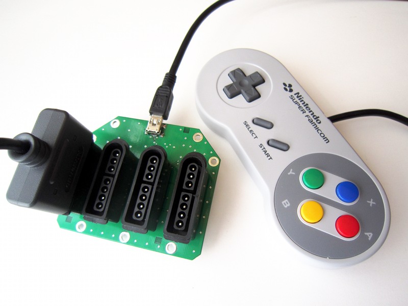
To make sure the adapter would be worth the effort to build, I decided to make a four player version. As I had already solved the electronic and software sides of the project (see 4nes4snes), I mostly had to focus on building the nice enclosure presented on this page.
Concept
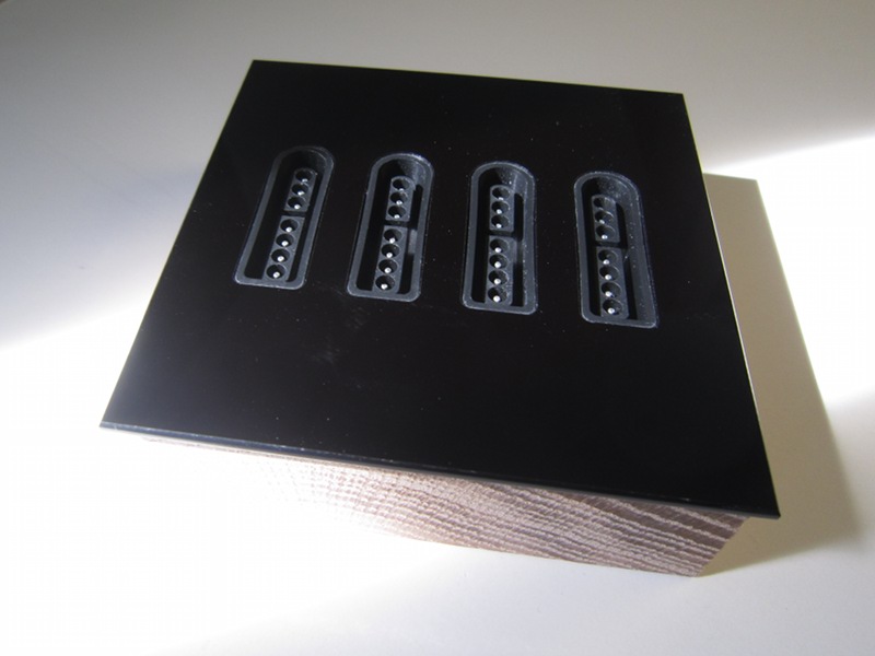
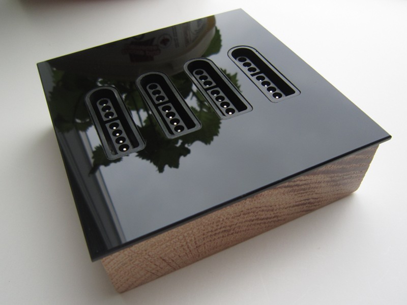
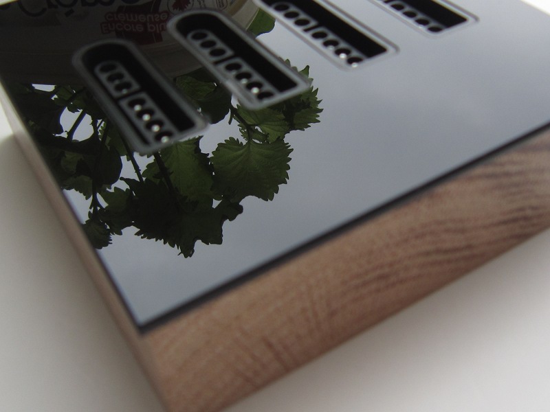
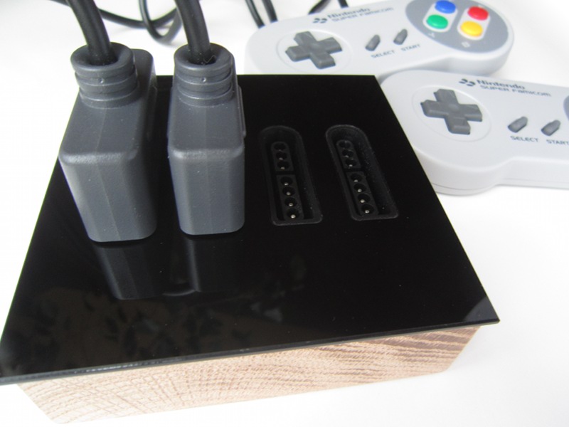
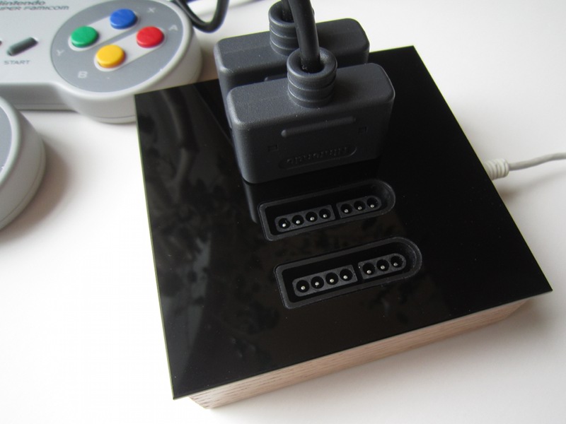
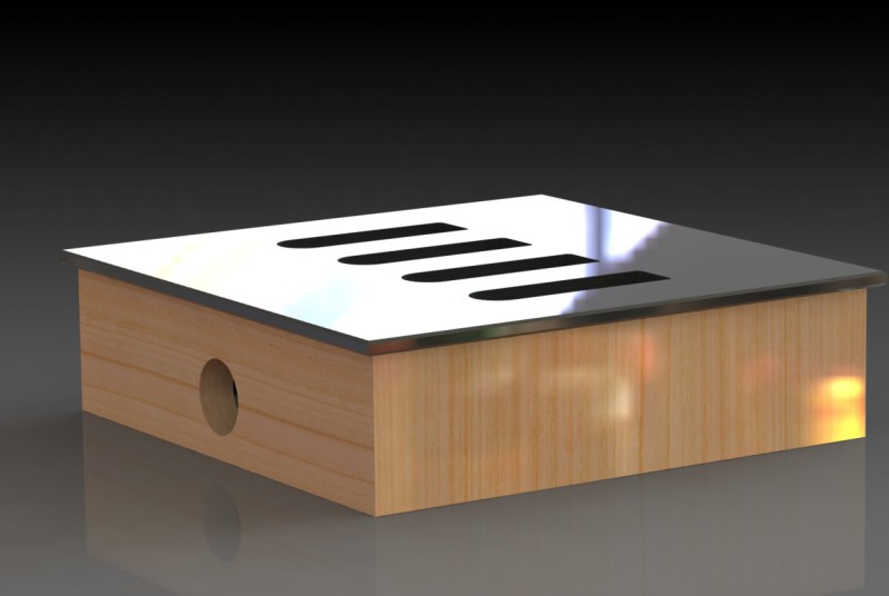
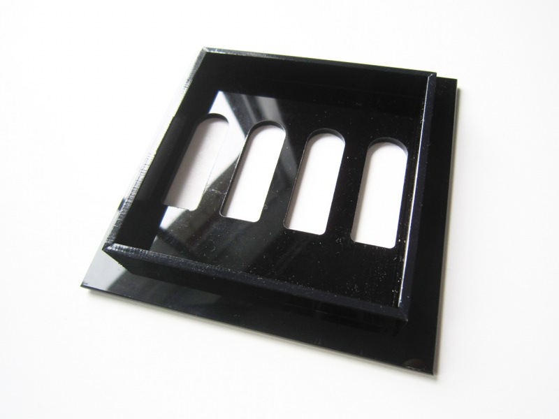
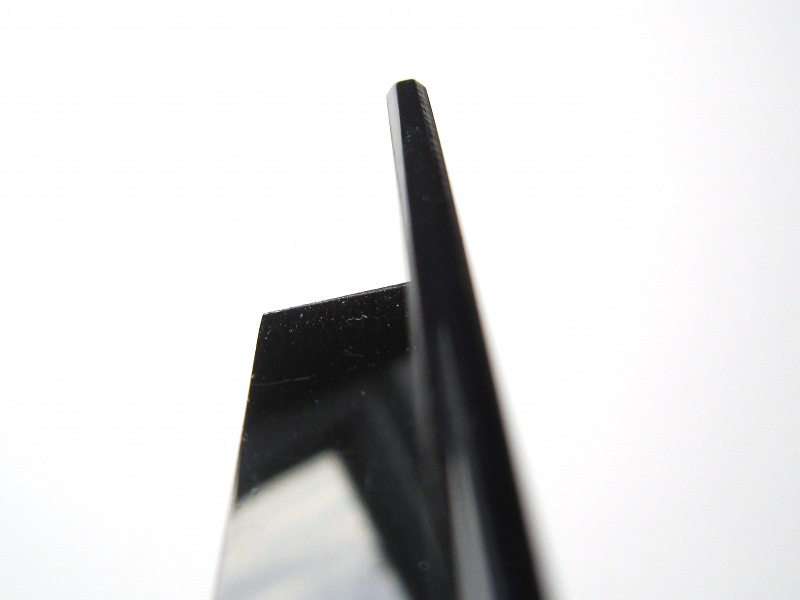
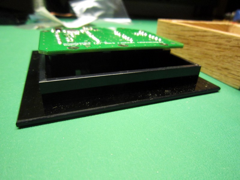
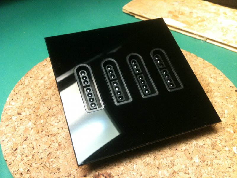
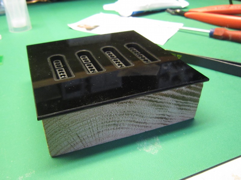
The concept I came up with uses a black acrylic sheet with openings cut to fit tightly around the SNES connectors. The sheet border has a double chamfer which softens the edges, to the touch as much as visually.The top acrylic part is glued to a wooden base which also holds the circuit board. The board is designed such that the distance between connectors matches the acrylic cover openings.
In the 3D model, I did not complete the design of the wooden box nor did I plan a way to hold the circuit board in place. I just decided to improvise those details later, during the build.
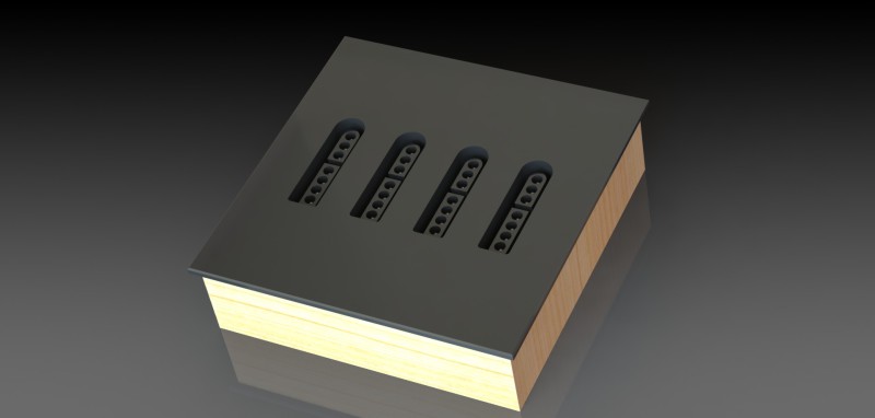
The concept
The concept
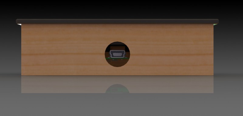
USB connector
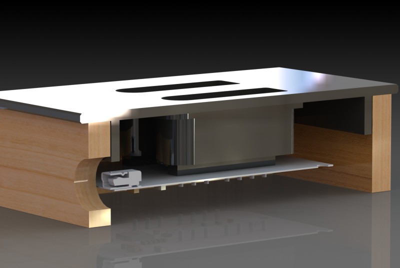
Section view
Cover
I drew the cover in a way making it possible to build it by cutting the required parts in an acrylic sheet. The inner frame is assembled using glue. Its purpose is to help centering the cover with the wood base, but also to offer a large surface for glue.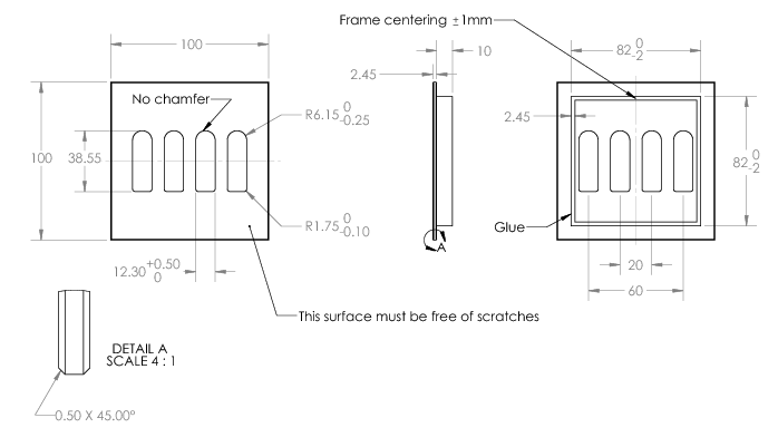
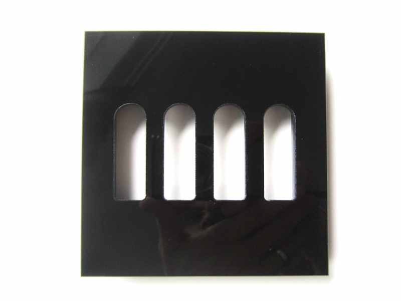
I had a small quantity produced by a plastic company. The result is very good, and certainly much better than I could attain with the tools I currently own. (Without CNC equipment, I think the cutouts with radii for the connectors would be difficult [but of course, not impossible])
| Four SNES controller to USB circuit |
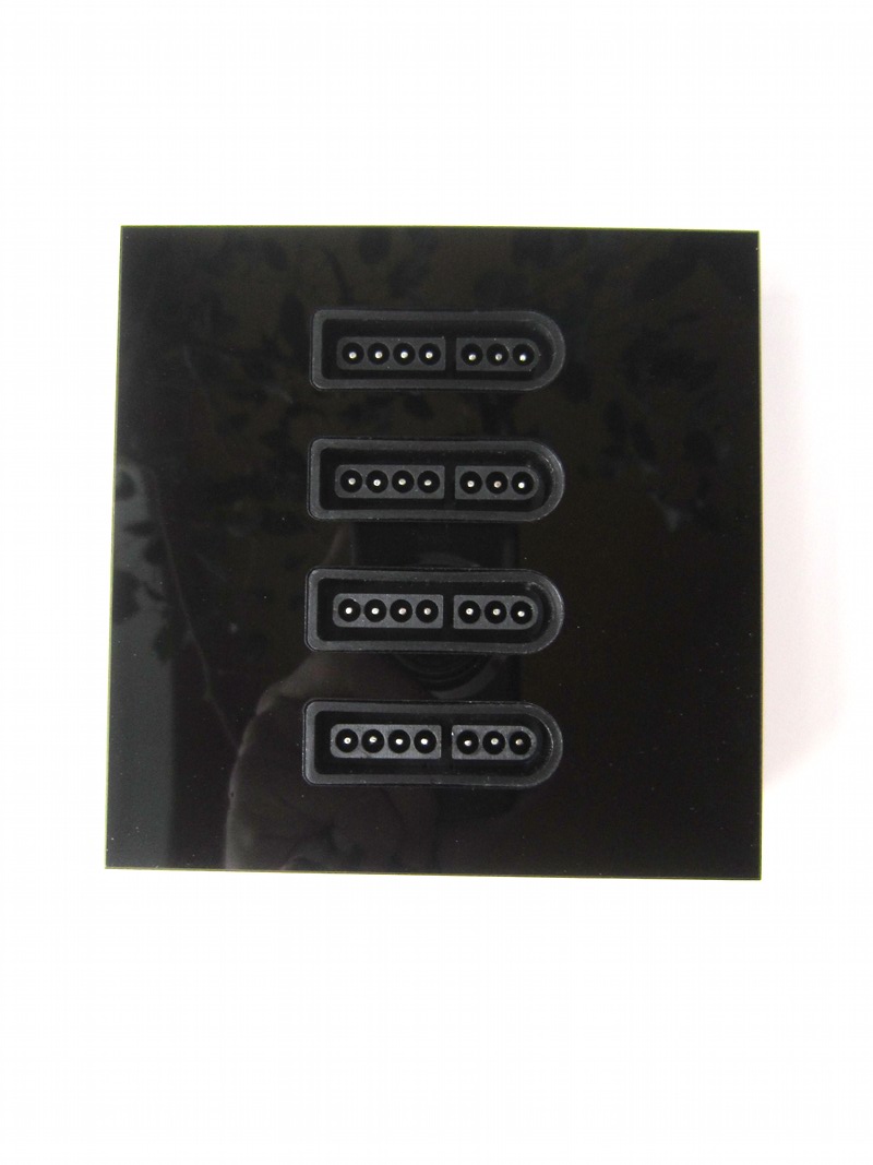
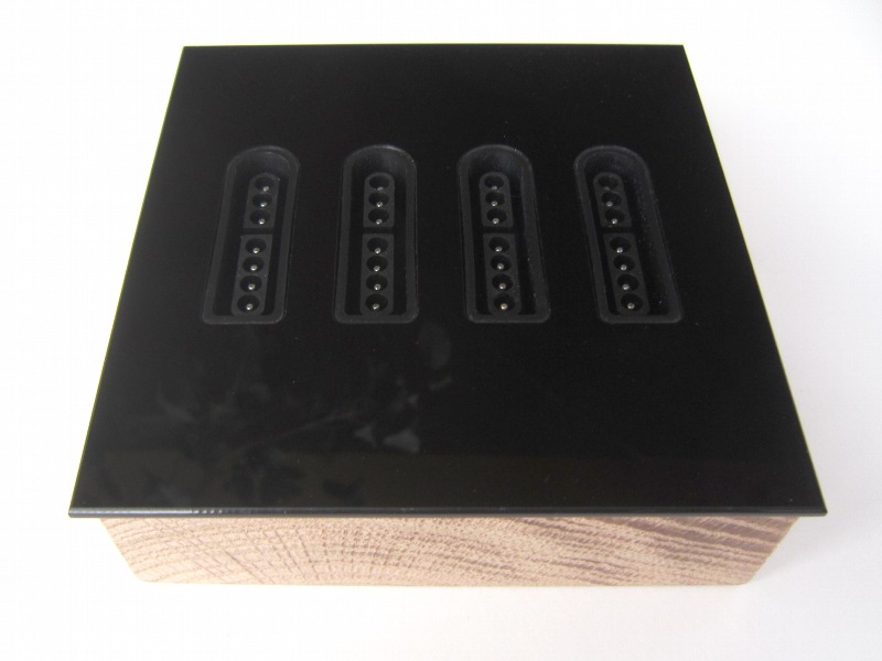
| Acrylic cover for four SNES to USB circuit |
Box
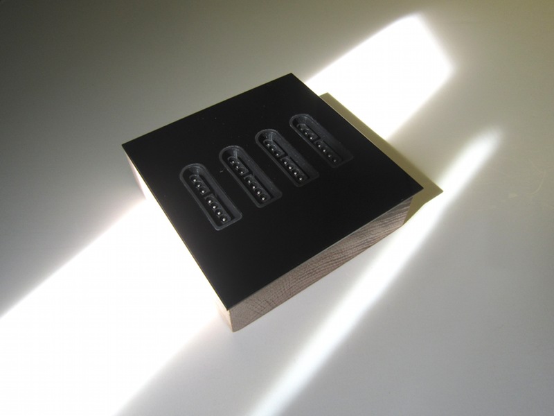
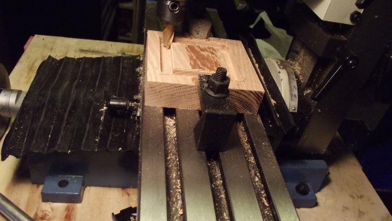
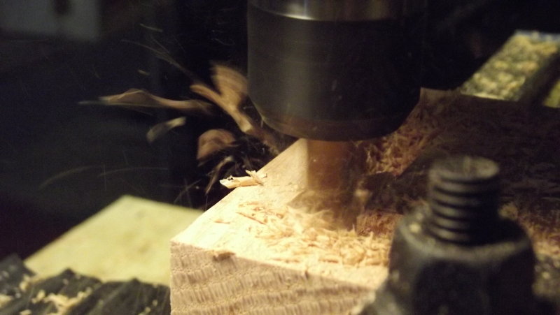
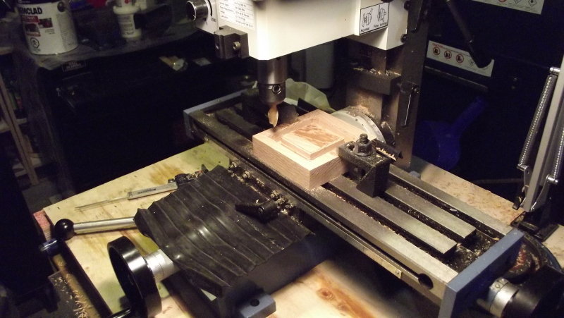
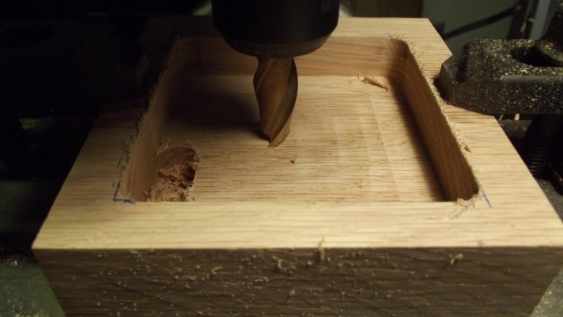
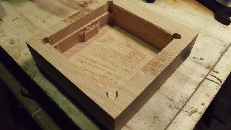
For the wooden base, I decided to try hollowing out a piece of oak by milling. With this technique, no assembly or gluing is necessary. And the faces of the piece all have very different looks (transverse and tangential sections)It was the first time I worked with wood on my milling machine. It worked very well, but produced a great deal of dust. Obviously, working with expensive wood with this technique would be wasteful...
Milling
Milling
Milling
Milling
Milling
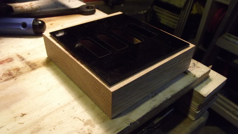
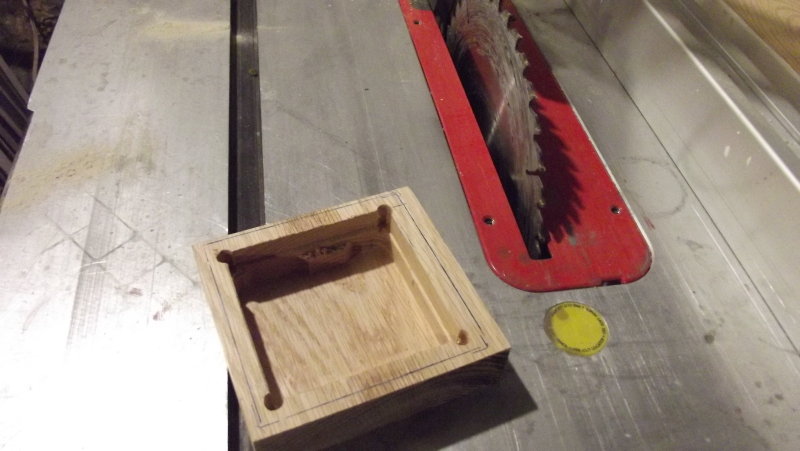
It fits!
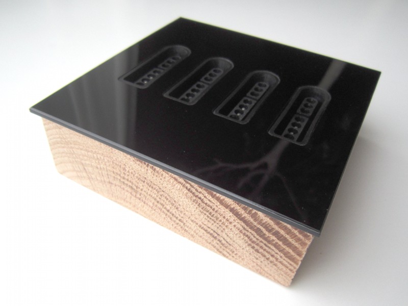
After making sure the acrylic cover would vit, I trimmed the sides using a circular saw. Doing so slightly burned the wood, but made the grain stand out in a way I liked. So I continued the work by boring a hole for the USB cable.
Trimming the sides
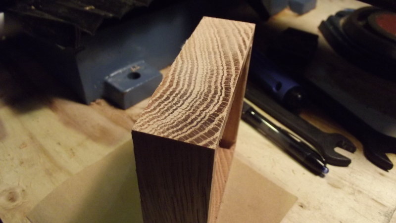
Wood grain
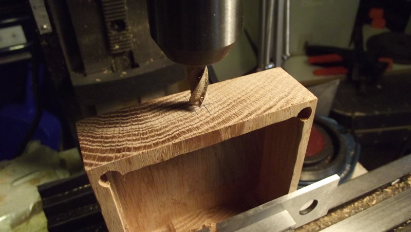
Boring the USB hole
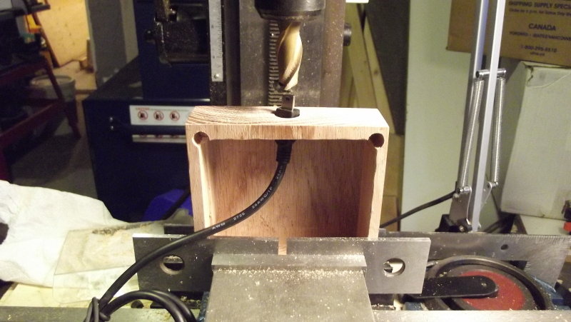
Boring the USB hole
I have a few layers of varnish:
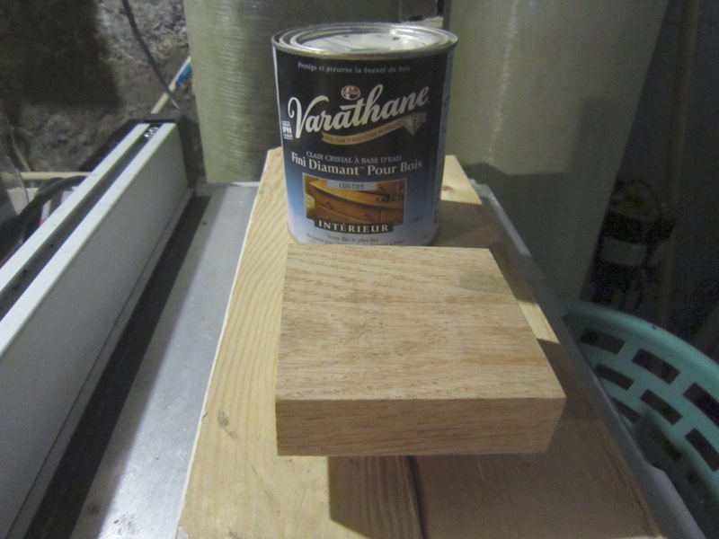
Varnishing...
Varnishing...
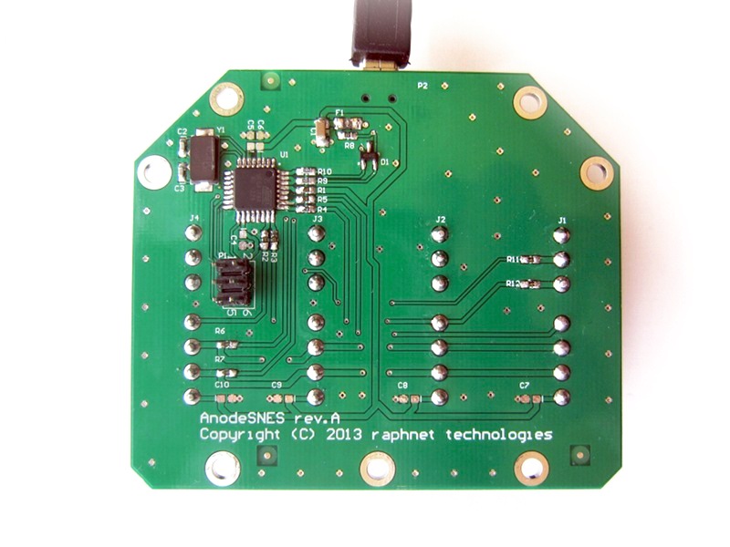
Circuit
The circuit is a simple implementation of my 4nes4snes project using an Atmega168a MCU. Up to 4 SNES connectors can be soldered. USB connectivity is provided by a mini-usb connector.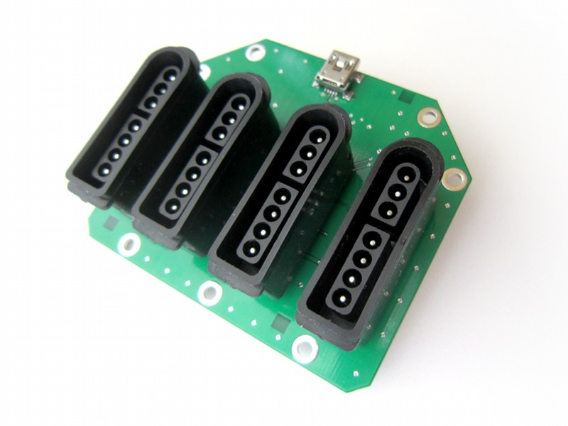
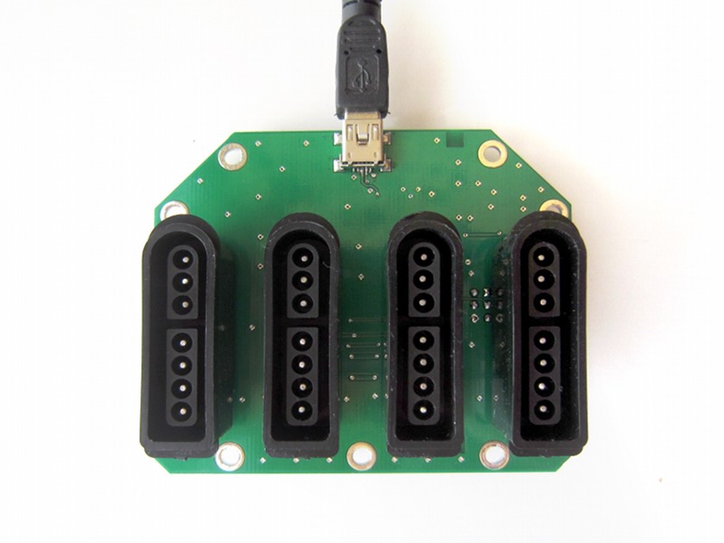
| Four SNES controller to USB circuit |
| Acrylic cover for four SNES to USB circuit |
Assembly
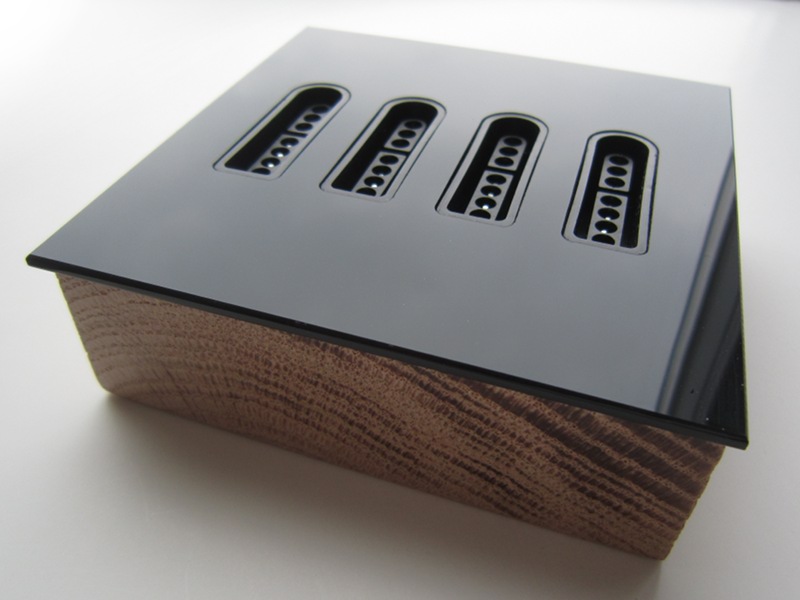
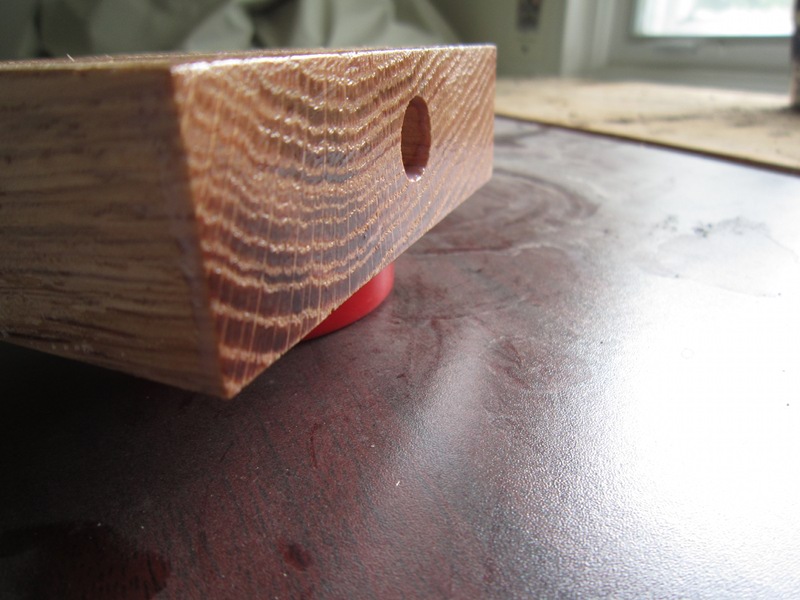
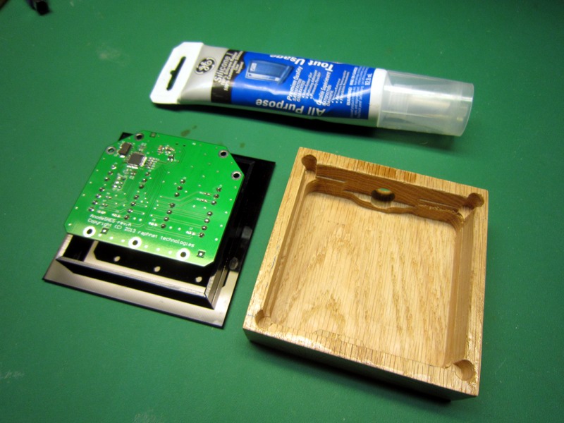
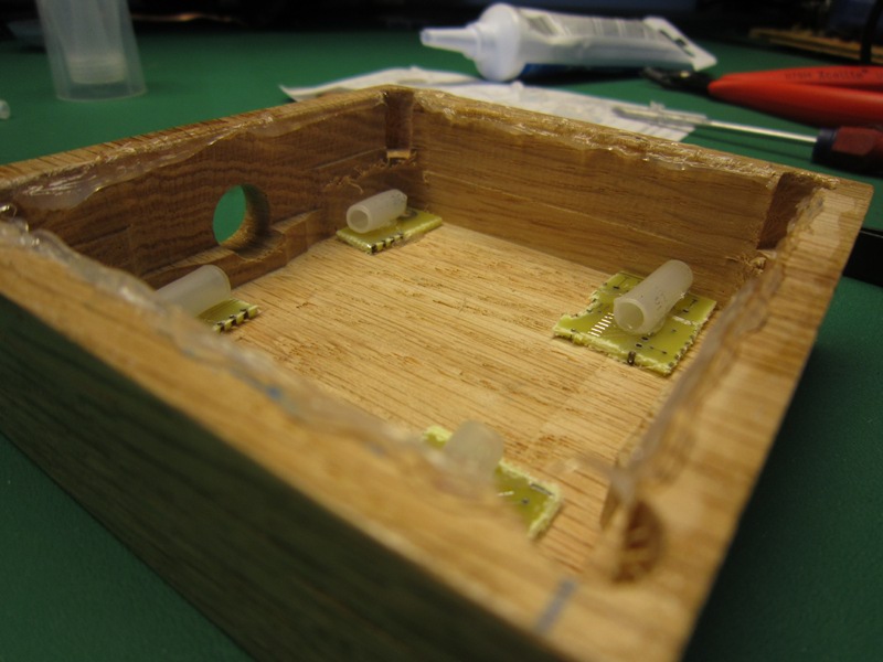
I inserted the SNES connectors in the acrylic cover opening and soldered the circuit board. To prevent the connectors and the circuit from falling inside the box, I improvised spacers using pieces of circuit boards and tubing.I then glued the cover in place using a silicone rubber adhesive. If I ever need to update the firmware, I will bore a new opening underneath the box to gain access to the ISP signals. But the adapter works very well as-is and the 4nes4snes projet is is based on is quite stable so I doubt I will ever need to do that.
Circuit and cover
Circuit and cover
Ready
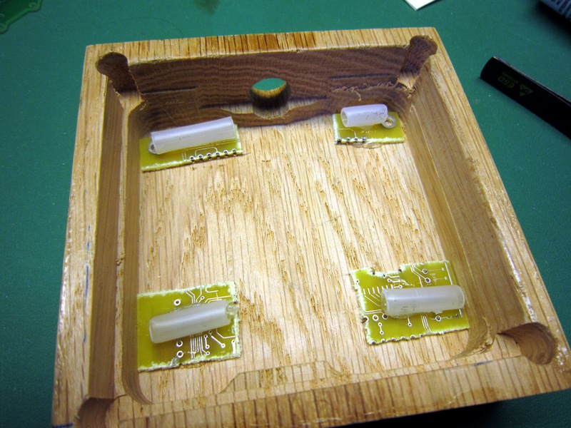
Improvised spacers
Silicon on the border
In place
Held in place for curing
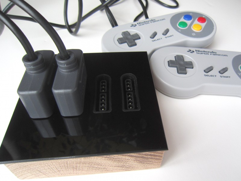
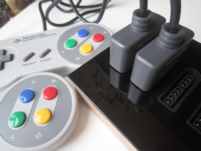
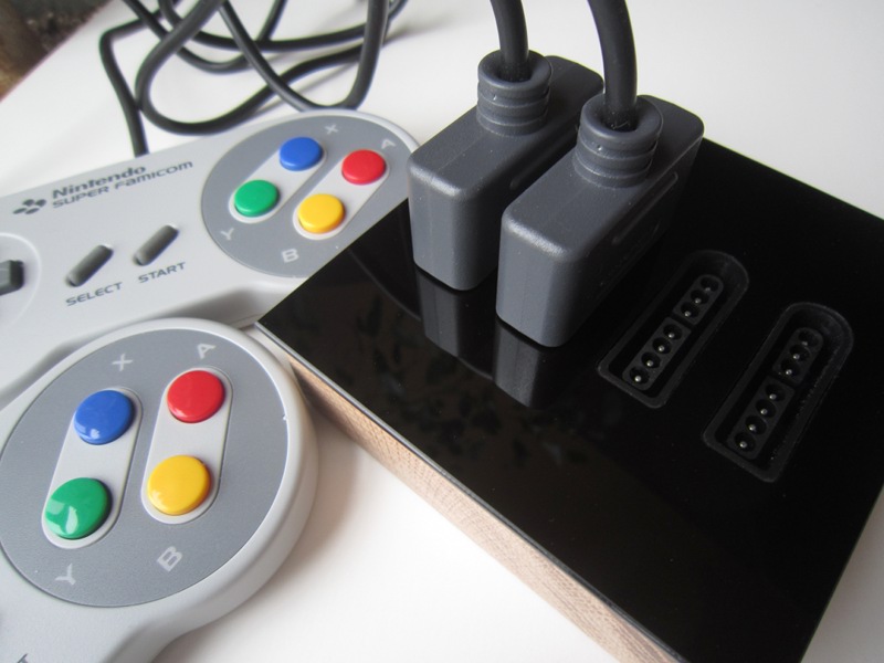
Result
I am very happy with the result. I like how similar it is to the original computer generated images!