USB_Game16: Joystick controller
Project overview

Application examples:
- Arcade style controller box, or integration in a PC-based arcade cabinet.
- Simple joystick adapters (1 wire per button) to USB. Ex: neo-Geo, Atari...
- With supporting software on the PC side, button inputs can serve other purposes than game control. The inputs can be connected to switches, limit-switch, alarm sensors. In any case, using a dedicated board such as this one is cleaner than modifying an off the shelf USB game controller.
Project specifications:
- 16 Inputs
- 12 Button inputs
- 4 Directional inputs (for switches or joystick)
- HID USB interface. Works as-is without installing special drivers on most platforms. (Linux, WinXP, Win7 32 and 64 bit).
- Easy wiring when implemented on the "Multiuse PCB3" board.
- Standard USB Type B connector.
- Through-hole solder points for easy wire installation.
- Widely spaced solder points prevent accidental bridging.
- Dedicated GND signal for each button for easier wiring. No need to connect all common wires together.
This project uses an ATmega8 microcontroller from Atmel. This microcontroller does not support USB in hardware so I used the software-only usb driver from Objective Development. This driver allows an AVR microcontroller such as the ATmega8 to talk USB with minimal external components. As a result, the interface can be built cheaply and easily
Wiring
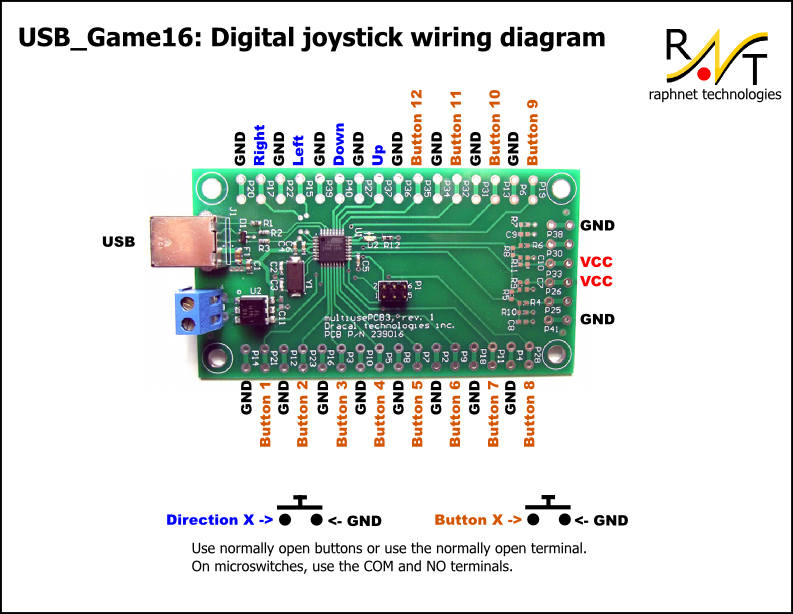
Wiring diagram
The firmware expects normally open (NO) buttons, so this is what should be used. On 3 terminal microswitches, the appropriate terminals should be wired (often marked "NO" and "COM").
Note: Normally Open = Conducting when pressed.
For reference, the following AVR inputs are used for the specified buttons:
| AVR name | Function | AVR name | Function |
|---|---|---|---|
| PORTD 4 | Up | PORTC 5 | Down |
| PORTC 4 | Left | PORTD 3 | Right |
| PORTC 3 | Button 12 | PORTC 2 | Button 11 |
| PORTB 5 | Button 10 | PORTC 1 | Button 9 |
| PORTD 5 | Button 8 | PORTB 4 | Button 7 |
| PORTB 3 | Button 6 | PORTB 2 | Button 5 |
| PORTB 1 | Button 4 | PORTB 0 | Button 3 |
| PORTD 7 | Button 2 | PORTD 6 | Button 1 |
Firmware
A microcontroller is a component which must be programmed in order to do something useful. So here is the hexfile which must be flashed into the microcontroller:usb_game16-1.0.hex
Many microcontrollers have what is called 'Fuse bytes'. In the case of the ATmega8a, there are two bytes: The high byte, and the low byte. Those bytes are used to configure some aspects of the microcontroller. What type of clock to use? Crystal? Resonator? Internal RC clock? Allow programming via ISP? It's very important to set the fuses to the right values. Using the wrong values can render your MCU unusable.
For this project, here are the appropriate fuse values:
high byte = 0xc9, low byte = 0x9f
For details about how to program an AVR, visit my AVR programming page.
Source code
The source code is released under the GPL license and compiles with avr-gcc. To prevent conflicts, please do not distribute modified version where the USB report descriptor has been modified without replacing the USB Vendor ID and Product ID by yours.usb_game16-1.0.tar.gz
Example 1: NeoGeo adapter
NeoGeo controllers use a standard DB15 and are extremely simple. There is a dedicated wire for each button plus a common wire. Wiring a NeoGeo controller to this circuit is therefore possible by following the following table:| DB15 | NeoGeo name | USB_Game16 name | Comment(s) |
|---|---|---|---|
| 1 | Common | Gnd (Any) | |
| 3 | Select | Button 6 | |
| 4 | D Button | Button 4 | |
| 5 | B Button | Button 2 | |
| 6 | Right | Right | |
| 7 | Down | Down | |
| 8 | +5v | VCC | Not always required |
| 9 | D Button | Button 4 | Duplicates pin 4 |
| 11 | Start | Button 5 | |
| 12 | C button | Button 3 | |
| 13 | A button | Button 1 | |
| 14 | Left | Left | |
| 15 | Up | Up |
Example 2: Arcade controller
Here is a 4 button arcade controller example. Since I only had buttons on hand (no joystick), I chose to experiment with 4 buttons layed out in a cross pattern (inspired from a D-Pad). It was difficult to use at first and I was thinking maybe this was a bad idea. But after a few minutes, I noticed that I was already used to it and that it was not so bad...
As we cas see here, I simply soldered the wires to the microswitches. Of course, maintenance will be slightly difficult...


I plan to add more buttons and to improve the button placement. Also, I will try to do (or more likely have someone do) a more artistic finish. To be continued...
Disclaimer
I cannot be held responsible for any damages that could occur to you or your equipment while following the procedures present on this page. Also, I GIVE ABSOLUTELY NO WARRANTY on the correctness and usability of the informations on this page. Please note, however, that the procedures above have worked in my case without any damages or problems.Now you cannot say that I did not warn you :)