Atari Jaguar controller to USB adapter
Project overview
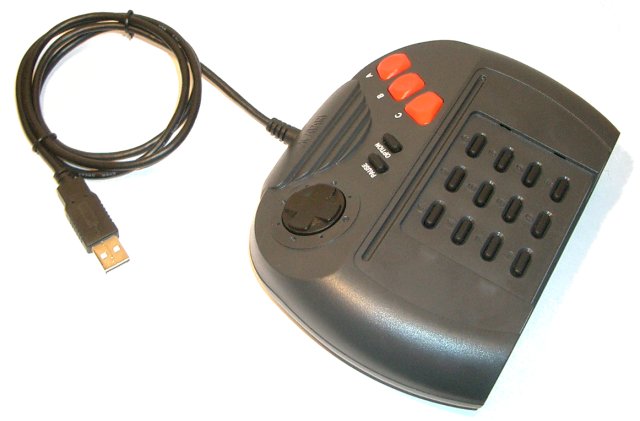
 I had to convert an Atari Jaguar controller to USB for a customer. As usual,
I decided to make the schematic and firmware for this project available to everyone.
I had to convert an Atari Jaguar controller to USB for a customer. As usual,
I decided to make the schematic and firmware for this project available to everyone.Specifications:
- No drivers required. Implements a standard USB HID device.
- Tested under Windows and Linux.
- All 17 buttons are usable.
- Works great in Virtual Jaguar.
| Controller Button | PC Button |
|---|---|
| A | 1 |
| B | 2 |
| C | 3 |
| Option | 4 |
| Pause | 5 |
| 1 | 6 |
| 2 | 7 |
| 3 | 8 |
| 4 | 9 |
| 5 | 10 |
| 6 | 11 |
| 7 | 12 |
| 8 | 13 |
| 9 | 14 |
| * | 15 |
| 0 | 16 |
| # | 17 |
Picture Gallery
Jaguar controller with surface mount circuit installed inside:

Screenshots:

Under Windows
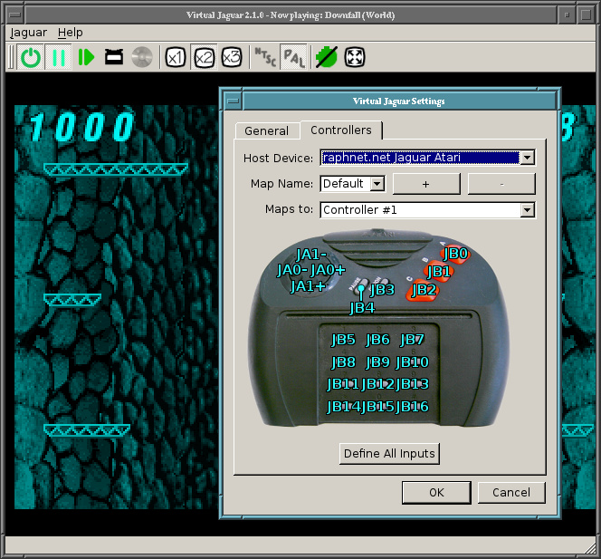
With Virtual Jaguar
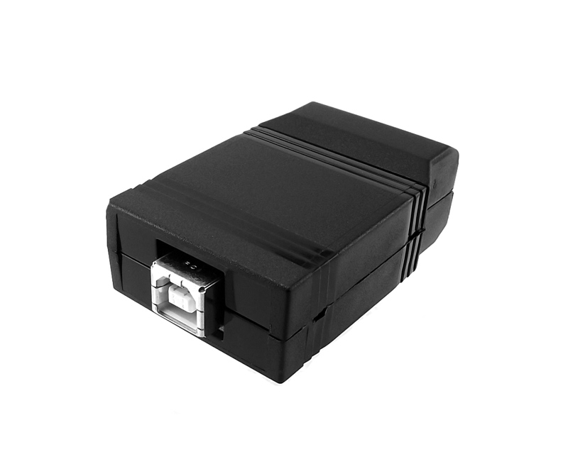
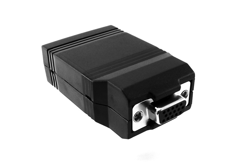
Ready to use Jaguar controller to USB adapter from my online store:
Schematic
I used my usual Atmega8 circuit with a custom firmware using the Objective Development AVR-USB device implementation.Here is the core schematic. For wiring the controller, use the table below.
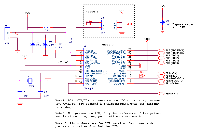
| I/O Micro. | #pin HD15 | Couleur | Description |
|---|---|---|---|
| PC5 | 1 | Brown | Column [N/A,opt,3,6,9,#] |
| PC4 | 2 | Red | Column [N/A,C,2,5,8,0] |
| PC3 | 3 | Orange | Column [N/A,B,1,4,7,*] |
| PC2 | 4 | Yellow | Column [Pause,A,East,West,South,North] |
| PC1 | 6 | Blue | Row [Pause,N/A,N/A,N/A] |
| PC0 | 10 | Black | Row [A,B,C,opt] |
| PB5 | 11 | Grey | Row [East,1,2,3] |
| PB4 | 12 | Pale Blue | Row [West,4,5,6] |
| PB3 | 13 | Pink | Row [South,7,8,9] |
| PB0 | 14 | White | Row [North,*,0,#] |
| VCC | 7 | Green | Power |
| GND | 9 | Purple | Power |
Component list:
| Ref | Description |
|---|---|
| U2 | Atmega8 microcontroller. ATMEGA8-16PC, ATMEGA8-16PI, ATMEGA8-16PJ or ATMEGA8-16PU. Don't use an ATMEGA8L-*, the 12Mhz clock would be too high. |
| R1 | 1.5k resistor. Ordinary carbon film 1/4 watt resistors will do. |
| R2, R3 | 68 ohm resistors. Ordinary carbon film 1/4 watt resistors will do. |
| D2, D3 | 3.6 volts zener diodes. |
| Y1 | 12 Mhz crystal. |
| C2, C3 | 18 pf capacitors. If the crystal datasheet recommends another value, use it instead. |
| C1 | 1uf capacitor. Install it near the ATmega8 power pins. |
| J2 | 6 pin header, 2.54mm spacing. Needed for programming the ATmega8. |
For the USB connection, just strip the USB cable and solder the wires directly to the board. USB uses standard wire colors, but beware of cheap cables using non-standard color codes.
| Color | Description | |
|---|---|---|
| Red | +5 volts | |
| Black | Ground | |
| Green | D+ | |
| White | D- |
Firmware
| Version v1.2 November 20, 2016 (Sunday) |
|---|
| Atmega168 support |
| File(s): jaguar_usb-1.2.tar.gz (91.9 KB) jaguar_usb-1.2-atmega8.hex (7.4 KB) jaguar_usb-1.2-atmega168.hex (7.7 KB) |
Show previous releases...
| Version v1.1 January 28, 2015 (Wednesday) |
|---|
Maintenance release:
|
| File(s): jaguar_usb-1.1.tar.gz (91.2 KB) jaguar_usb-1.1.hex (7.6 KB) |
| Version v1.0 January 23, 2009 (Friday) |
|---|
| Initial release |
| File(s): jaguar_usb-1.0.tar.gz (72.5 KB) jaguar_usb-1.0.hex (8.1 KB) |
 This project is also available on GitHub!
To request features, report issues or contribute, you may send me an email or use the GitHub repository:
https://github.com/raphnet/jaguar_usb
Pre-compiled files (.hex format) are also available.
Many microcontrollers have what is called 'Fuse bytes'. In the case of the ATmega8, there are two bytes: The high byte, and the low byte. Those bytes are used to configure some aspects of the microcontroller. What type of clock to use? Crystal? Resonator? Internal RC clock? Allow programming via ISP? It's very important to set the fuses to the right values. Using the wrong values can render your MCU unusable.
For this project, here are the appropriate fuse values:
high byte = 0xc9, low byte = 0x9f
For details about how to program an AVR, visit my AVR programming page.
 Pre-programmed Atmega8 (DIP package) available
PCB for surface-mount
The surface-mount version uses my Multiuse PCB2 circuit. Here's a picture of this circuit with a few labels to ease wiring: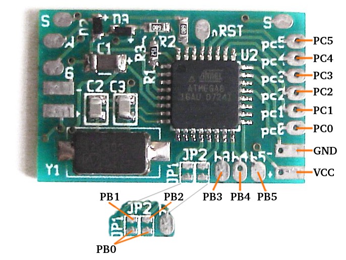
Disclaimer
I cannot be held responsible for any damages that could occur to you or your equipment while following the procedures present on this page. Also, I GIVE ABSOLUTELY NO WARRANTY on the correctness and usability of the informations on this page. Please note, however, that the procedures above have worked in my case without any damages or problems.Now you cannot say that I did not warn you :)