Atari/SMS/Genesis joystick/controller/multi-tap to USB adapter
The idea
 For playing good old games with an emulator, nothing beats the original controllers. There
was a time where many game consoles and computers used a DB9 connector for joysticks and controllers. This
projects aims to adapt all these controllers on USB ports.
For playing good old games with an emulator, nothing beats the original controllers. There
was a time where many game consoles and computers used a DB9 connector for joysticks and controllers. This
projects aims to adapt all these controllers on USB ports.Many people like me have been happy doing this with simple homebuilt parallel port adapters for years but unfortunately, parallel ports are becoming less common these days (Some computers dont have any parallel ports!). Also, modern game controllers uses USB.
That's why I decided to build my own DB9 controller to USB adapter. At the moment, the following controllers are supported:
- 1 Button Atari and compatibles
- 2 Button controllers, such as Sega master system
- Genesis controllers, 3 and 6 button flavors (Tested: Sega models 1650, mk-1653 and mk-1470, Fighter Stick SG-6)
- Sega multi-tap (Team Player) for Genesis. See the Genesis
multi-taps information page for a list of supported models.
- Up to 4 genesis controllers (6 and/or 3 button versions) can be used simultaneously.
- They appear as one big controller with 8 axes and 32 buttons under Linux
- Under Windows, they appear as 4 separate game controllers.
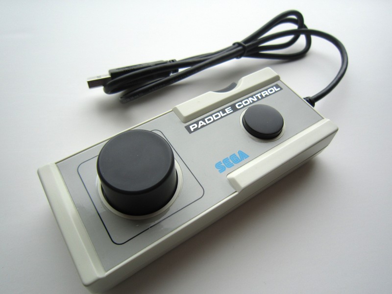
- HPD-200 Sega Paddle Controller (see features)
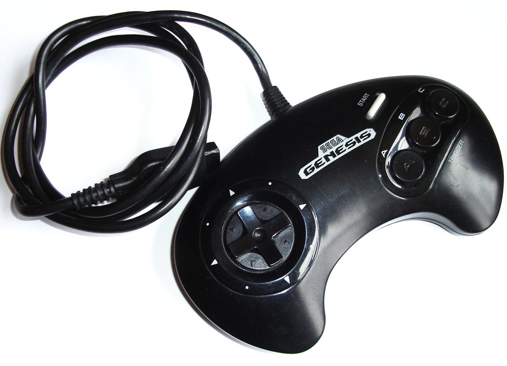
Genesis 3 buttons

Genesis 6 buttons
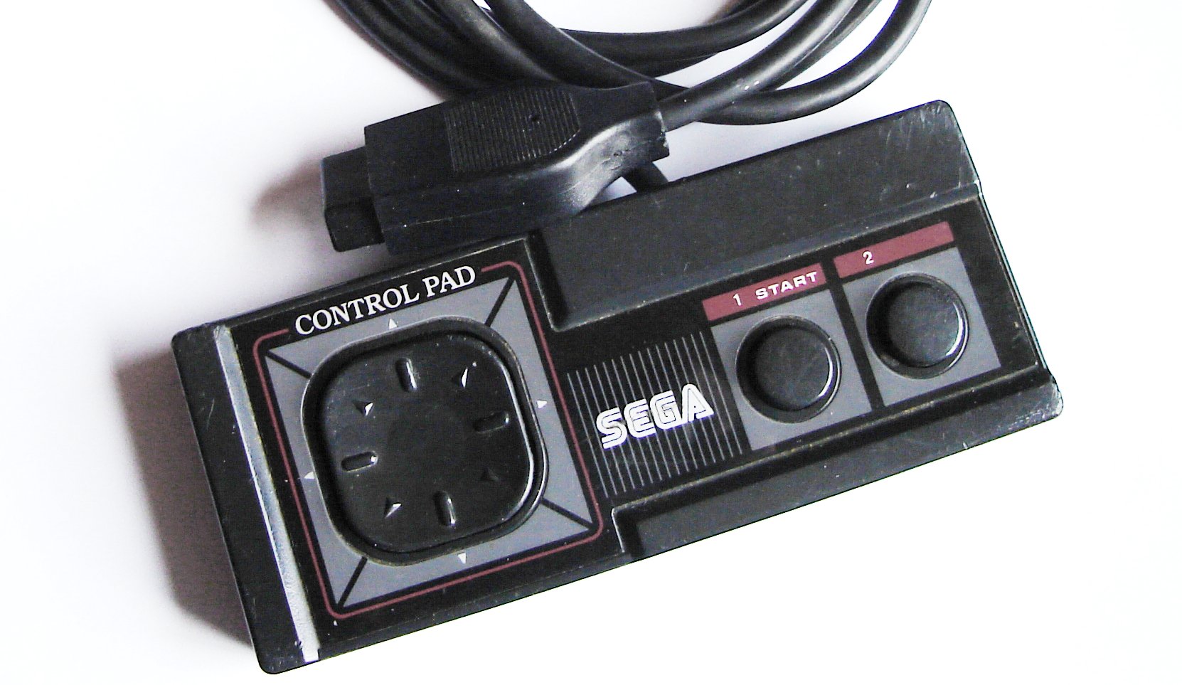
Sega master system
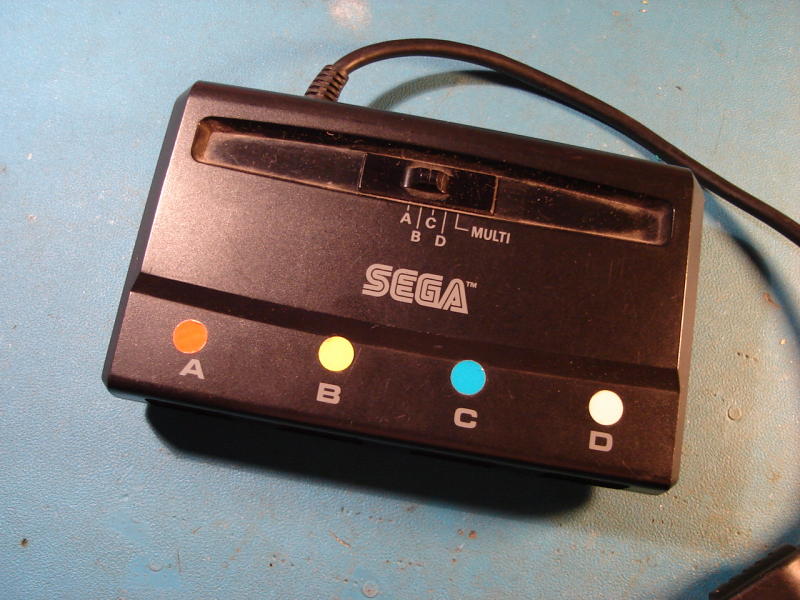
Multi-tap MK-1654
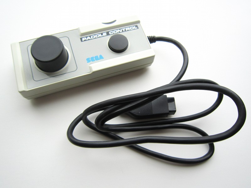
Sega paddle controller HPD-200
However, due to the way USB works, the adapter is a little more complicated than the old parallel port versions.
Note: The project on this page can also be used for NES and SNES controllers. Visit the SNES/NES gamepad (and mouse) to USB adapter project page.
 Ready-built Atari to USB adapters available
Project overview
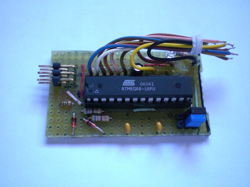
I first built my adapter using an ATmega8 microcontroller from Atmel, but the new Atmega8a also works perfectly without requiring any changes to the code or fuse settings. These microcontrollers do not have support for USB in hardware so I used the software-only usb driver from Objective Development. This driver allows an AVR microcontroller such as the ATmega8 to talk USB with minimal external components. As a result, the interface can be built cheaply and easily, thanks to the low component count.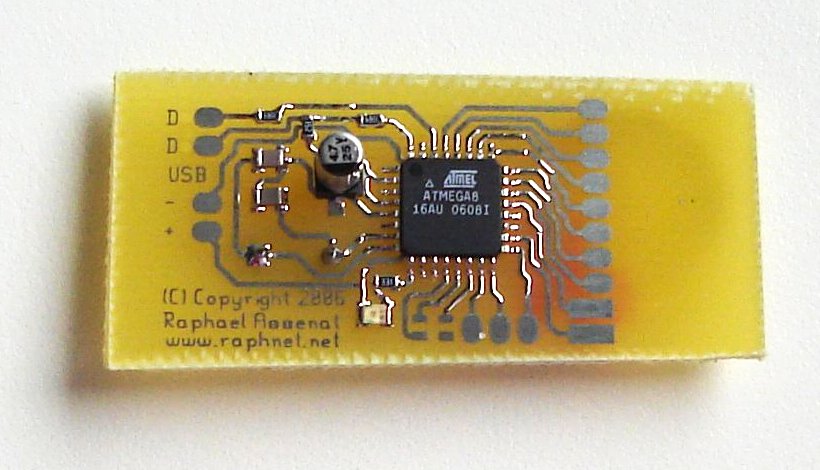 Depending on your skills, you may build the interface using breadboard and thru-hole components or
the surface mount version, using the PCB artwork I provide. I also sell pre-assembled PCBs
and pre-programmed Atmega8 (dip package only).
Depending on your skills, you may build the interface using breadboard and thru-hole components or
the surface mount version, using the PCB artwork I provide. I also sell pre-assembled PCBs
and pre-programmed Atmega8 (dip package only).That's right, since the USB standard defines device classes. I'm using the human input device (HID) which allows me to tell to the computer that the connected USB device is a joystick and has 2 axis and 4 or 8 buttons. Another nice thing about this is that the adapter should work with all operating systems supporting HID devices. (I tested and it works at least on Win98, Win2K, WinXP and Linux)
HPD-200 Features
 Support for this slightly unusual controller has been
implemented for a customer. As per his request, I made it possible to use the two buttons independently (normally,
both button are equivalent) and I also implemented 4 different operation modes which makes it possible to
alter the behaviour of the controller for greater compatiblity.
Support for this slightly unusual controller has been
implemented for a customer. As per his request, I made it possible to use the two buttons independently (normally,
both button are equivalent) and I also implemented 4 different operation modes which makes it possible to
alter the behaviour of the controller for greater compatiblity.The operation mode is selected by holding buttons while connecting the controller as described in the following table:
| Mode | Description |
|---|---|
| 0 | Default. The two buttons are equivalent and the left-right axis is controlled. |
| 1 | Active if the round button was held down at startup. Both buttons are still equivalent but the up-down axis is controlled instead. |
| 2 | Active if the side button was held down at startup. In this mode, buttons are independent and the left-right axis is controlled. |
| 3 | Active if both buttons were held down at startup. In this mode, buttons are independant and the up-down axis is controlled. |
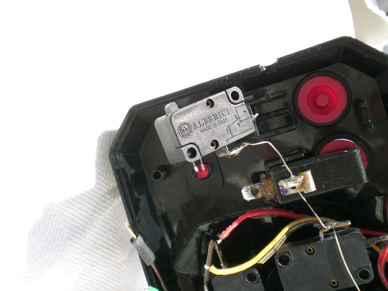
In order to have two independant buttons, the side button must connect the PB4 MCU input to GND when pressed. As an example, here are two pictures of an HPD-200 controller converted to USB:

Schematic
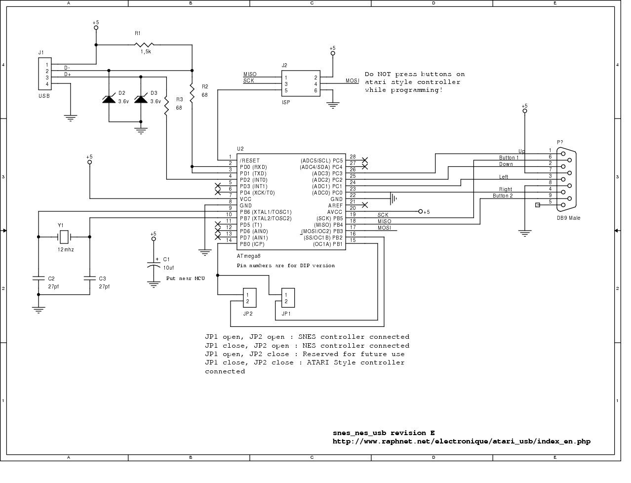
Here is the modern version of the schematic (for firmware 1.5 and up):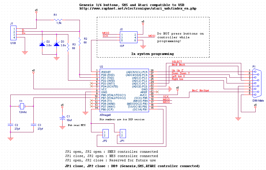
Here is the old versions of the schematic (for firmwares up to 1.4):
revE-atari.png
sch-revE-atari.pdf
Component list:
- U2: Atmega8 or Atmega8a microcontroller. ATMEGA8-16PC, ATMEGA8-16PI, ATMEGA8-16PJ or ATMEGA8-16PU. Dont use an ATMEGA8L-*, the 12Mhz clock would be too high.
- R1: 1.5k resistor. Ordinary carbon film 1/4 watt resistors will do.
- R2, R3: 68 ohm resistors. Ordinary carbon film 1/4 watt resistors will do.
- D2, D3: 3.6 volts zener diodes.
- Y1: 12 Mhz crystal.
- C2, C3: 27 pf capacitors. If the crystal datasheet recommends another value, use it instead.
- C1: 10uf capacitor. Install it near the ATmega8.
- JP1, JP2: Jumpers. You can also use dip switches, ordinary switchs or solder bridges.
- J2: 6 pin header, 2.54mm spacing. Needed for programming the ATmega8.
- P1: DB9 male connector.
For the USB connection, just strip the USB cable and solder the wires directly to the board. USB uses standard wire colors:
| Color | Description | |
|---|---|---|
| Red | +5 volts | |
| Black | Ground | |
| Green | D+ | |
| White | D- |
Programming the microcontroller
A microcontroller is a component which must be programmed in order to do something useful. So here is the hexfile which must be uploaded to the microcontroller:| File | Comments |
|---|---|
| nes_snes_db9_usb-1.9.hex |
|
| nes_snes_db9_usb-1.8.hex |
|
| nes_snes_db9_usb-1.7.hex |
|
| nes_snes_db9_usb-1.6.hex |
|
| nes_snes_db9_usb-1.5.hex |
|
| snes_nes_atari_usb-1.4.hex |
|
| snes_nes_usb-1.3.hex |
|
| snes_nes_usb-1.2.hex | Added Snes mouse support. |
| snes_nes_usb-1.1.hex | Reworked the report descriptor for better behaviour under Windows and MacOS X |
| snes_nes_usb-1.0.hex | Initial release. |
Many microcontrollers have what is called 'Fuse bytes'. In the case of the ATmega8, there are two bytes: The high byte, and the low byte. Those bytes are used to configure some aspects of the microcontroller. What type of clock to use? Crystal? Resonator? Internal RC clock? Allow programming via ISP? It's very important to set the fuses to the right values. Using the wrong values can render your MCU unusable.
For this project, here are the appropriate fuse values:
high byte = 0xc9, low byte = 0x9f
For details about how to program an AVR, visit my AVR programming page.
Source code
For those who wish to modify the device behaviour or add support for new type of gamepads, here is the source code. Starting with version 1.5, it is released under the GPL v2 license. Previous version were released under the Objective Development license, which is basically GPL + extensions to cover hardware. See License.txt for more information.| File | Comments |
|---|---|
| nes_snes_db9_usb-1.9.tar.gz |
|
| nes_snes_db9_usb-1.8.tar.gz |
|
| nes_snes_db9_usb-1.7.tar.gz |
|
| nes_snes_db9_usb-1.6.tar.gz |
|
| nes_snes_db9_usb-1.5.tar.gz |
|
| nes_snes_usb-1.4.tar.gz |
|
| nes_snes_usb-1.3.tar.gz |
|
| nes_snes_usb-1.2.tar.gz | Added SNES mouse support. |
| nes_snes_usb-1.1.tar.gz | Reworked the report descriptor for better behaviour under Windows and MacOS X |
| nes_snes_usb-1.0.tar.gz | Initial release. Snes and Nes support. |
Please contact me at raph@raphnet.net if you do useful changes.
Objective Development driver modifications:
The NES/SNES mode selection jumper changes the HID report descriptor. I had to modify Objective Development's usb driver to support this. Here is a diff against the usb driver from HIDKeys.2006-03-14:
usbdrv-diff
USB Vendor ID/Product ID pair:
Please do not re-use my VID/PID pair for derived or other projects. Instead, get your own. I bought my VID/PID pairs from mecanique, and they are much less expensive than the 2000$ US it cost to get a vendor ID from the usb implementers forum.
Printed Circuit Board for surface-mount version
 The surface mount version has many advantages:
- Very small (approximately 1"1/4 x 3/4" or 32mm x 20mm).
- Fits inside 3/4 pvc pipes. Ideal for installing inline with USB connector.
- Can be installed directly inside an Snes or Nes gamepad.
- Less wires to solder than on a breadboard. In some ways, it's easier to build.
- Looks more professional.
- You can use the board for other purposes. (After all, you have a reprogrammable MCU with USB and a few IO pins)
Here is a composite view of the PCB rev.C:
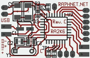
For reference, here is the composite view of rev.B: snes_nes_usb_pcb_revB.png
Here are the gerber files you can use to build your PCB(s):
Revision C: snesusb_revC.zip
Revision B: snes_nes_usb_PCB-revB.zip
Assembling the surface-mount version
Step 1: Use the composite view, the schematic and component list to find out where each component goes. Solder everything in place and inspect the board carefully for solder bridges. IMPORTANT: Do a solder bridge between PD1 and PD0 (see schematic).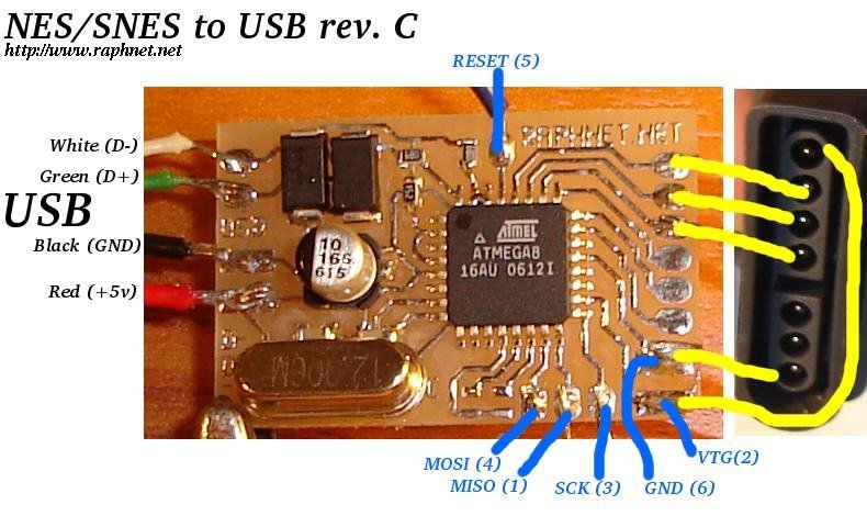 Step 2: Use the appropriate diagram on the left to solder the USB, ISP and controller/joystick
wires at the right places. The ISP cable can be built with a 2x3 header and a piece of flat cable. Pin numbers on diagram matches the standard atmel 6 pin AVR ISP.
Step 2: Use the appropriate diagram on the left to solder the USB, ISP and controller/joystick
wires at the right places. The ISP cable can be built with a 2x3 header and a piece of flat cable. Pin numbers on diagram matches the standard atmel 6 pin AVR ISP.
 Step 3: If you will be using a NES gamepad, close JP1 with a solder bridge
or a small piece of wire. For DB9 gamepads, close JP1 and JP2.
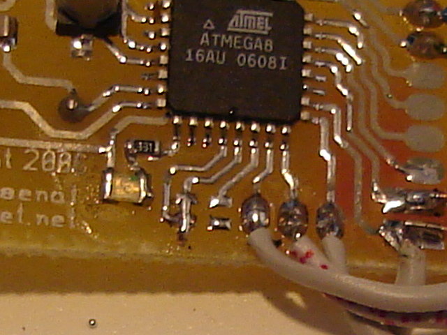
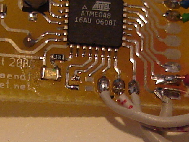
Refer to the pictures on the right for examples.
Step 3: If you will be using a NES gamepad, close JP1 with a solder bridge
or a small piece of wire. For DB9 gamepads, close JP1 and JP2.
Refer to the pictures on the right for examples.
Step 4: Connect the USB and ISP cables. Use you programmer to program the hexfile into the ATmega8. Next, set the fuses bytes (High byte=0xc9, low byte=0x9f).
Step 5: Test the adapter with a game. If all works well, you can remove the ISP cable if you dont plan to update the firmware. Now find a way to protect the PCB. You can fit it inside a little box, a piece of PVC pipe or a heat-shrink. Also, adding hot glue near the wires you soldered on the PCB will prevent the wires from breaking near the solder points.
Step 6: Have fun!
Pictures and screenshots
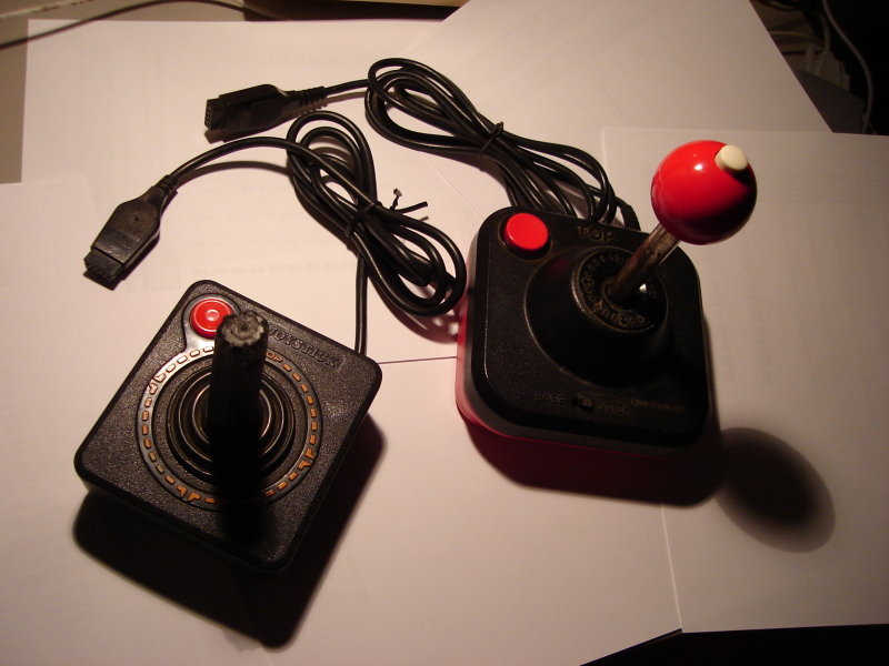 Here are two Atari style joysticks that work with this adapter.
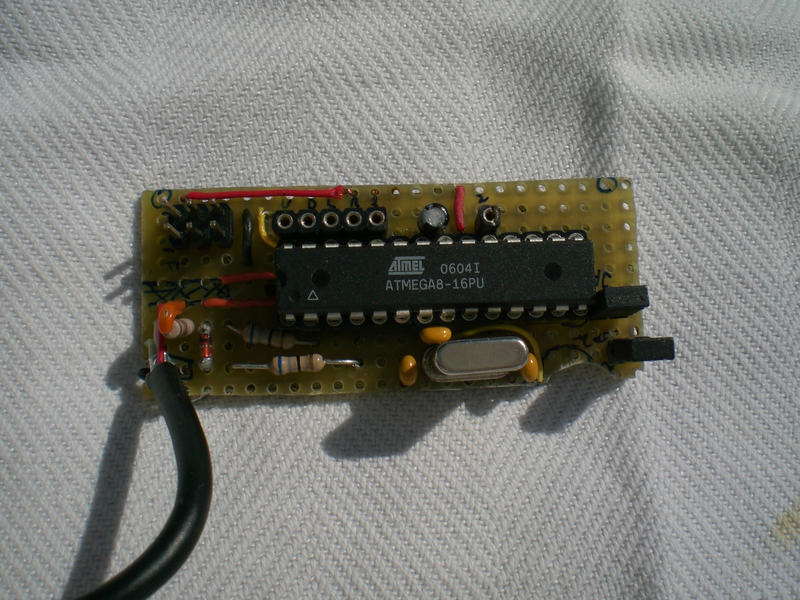
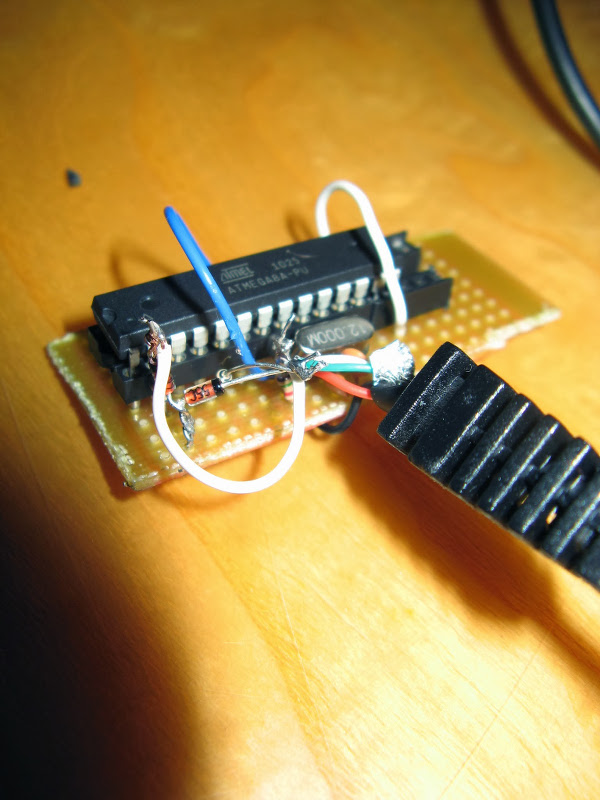
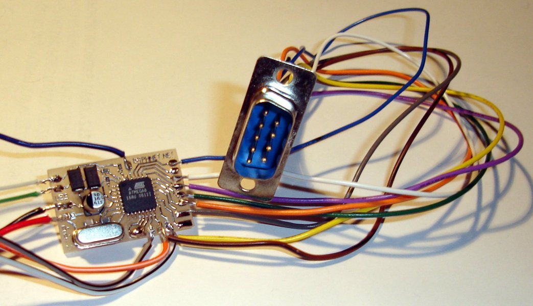 Here is my first adapter. It is built with the surface-mount PCB rev.C, a male DB9 and a couple of wires.
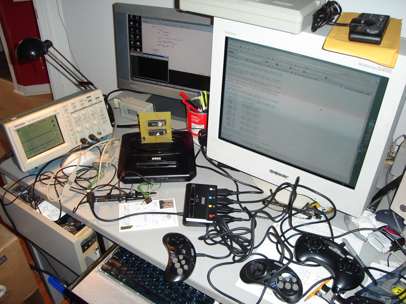 Here's what my desk looked like while I was figuring out how the multi-tap worked. Afterwards,
I wrote the following document explaining
how the multi-tap works.
Here's what my desk looked like while I was figuring out how the multi-tap worked. Afterwards,
I wrote the following document explaining
how the multi-tap works.
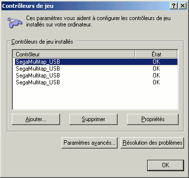 The multitap appears as 4 controllers in Windows.
Pictures from users
I seeing how others build my projects. Please send me your pictures and I post them here.September 25, 2016 (Sunday)
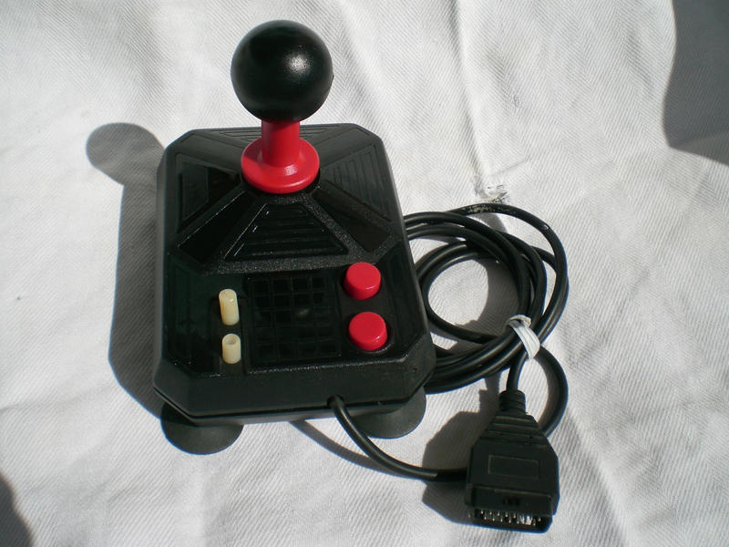
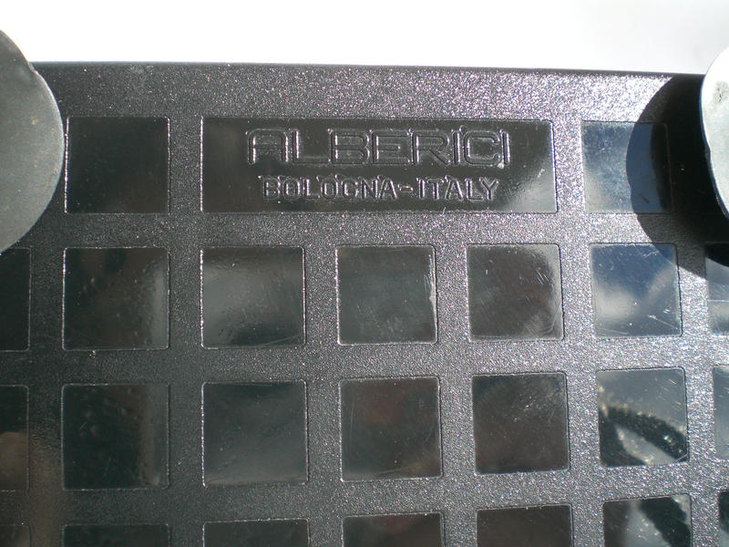
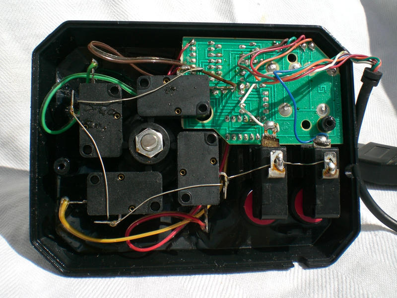
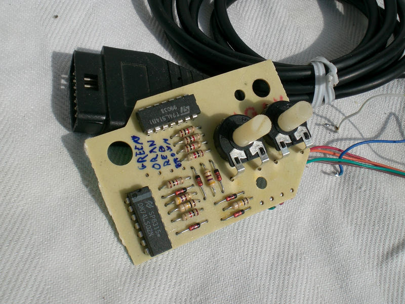
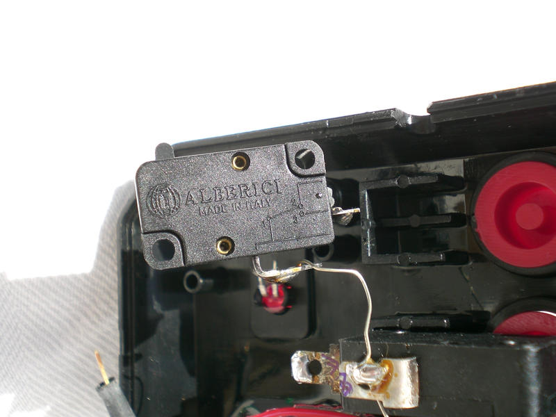
Filippo form Italy converted an Alberici joystick. They were famous in Italy, especially the DB9 connector version for Commodore 64. He got one of the DB15 model for PC and converted it to USB.

February 17, 2016 (Wednesday)
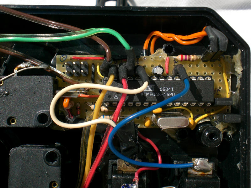
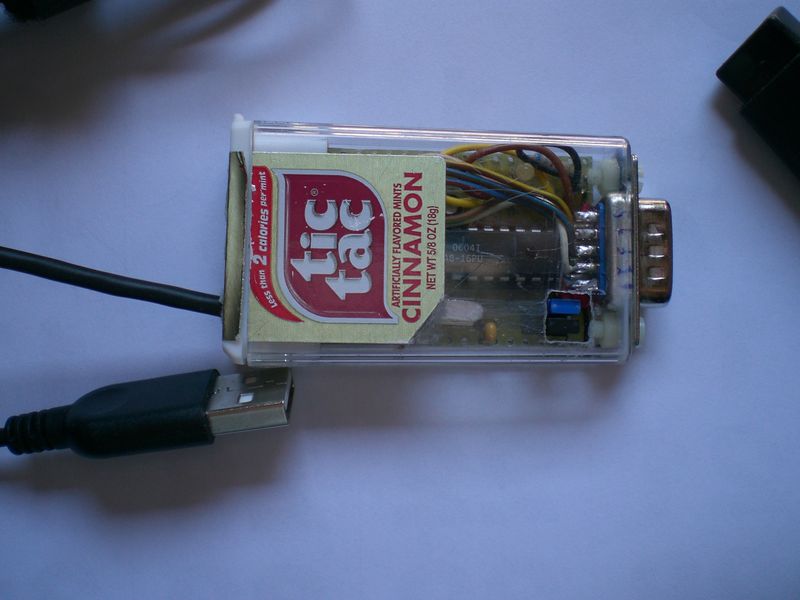
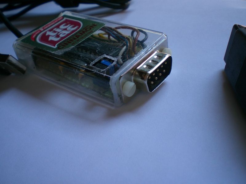
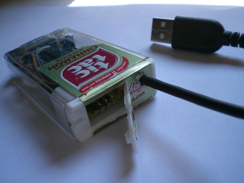
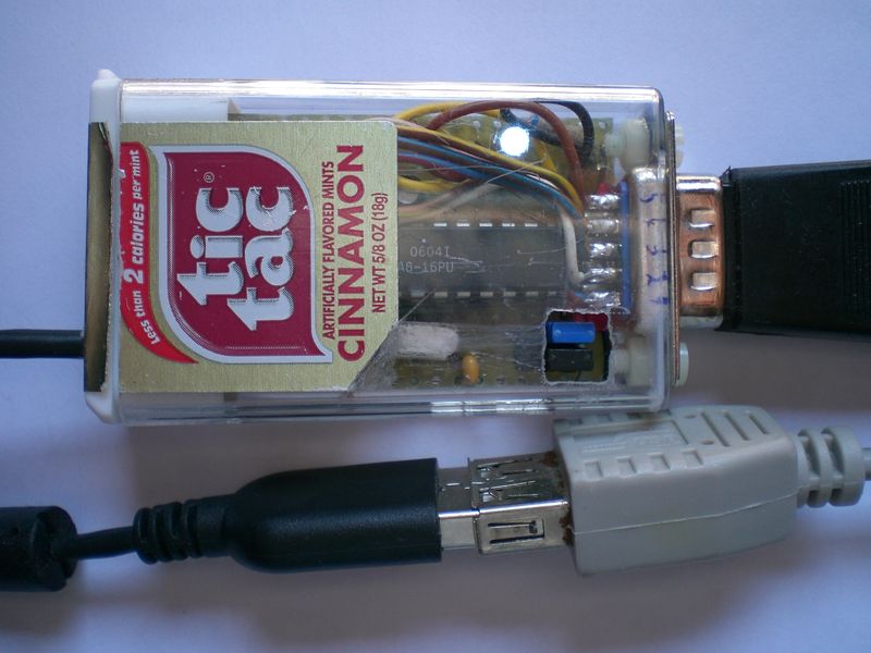
Filippo from Italy built the project into a small tictac box. He can now use his C=64 joysticks with VICE. I like the small access door for the ISP connector!
January 6, 2015 (Tuesday)
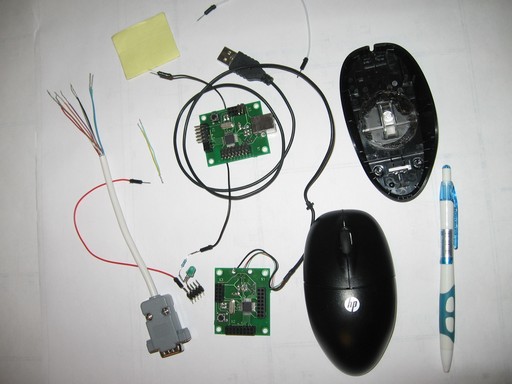
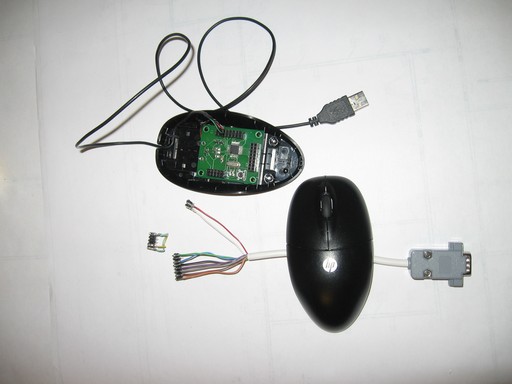
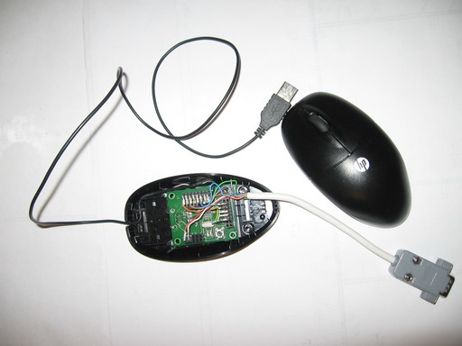
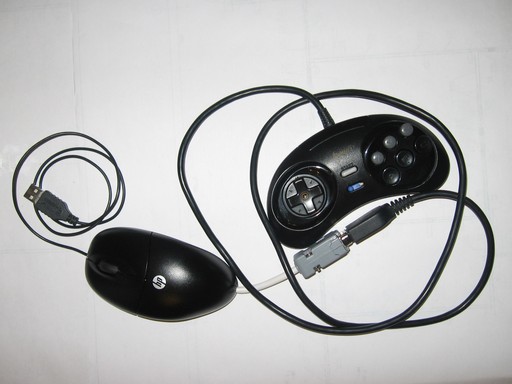
Roman Sysoev from russia built this adaptor using the casing of an HP mouse and an ARCAdaptor PCB - http://adapto.rs (Russian)

December 24, 2013 (Tuesday)
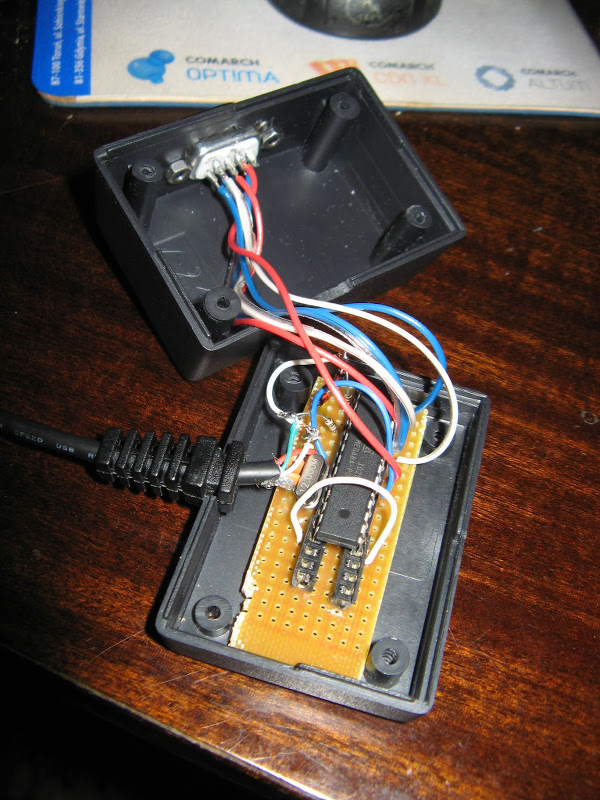
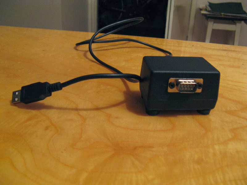
Slawomir Krysztowiak from Poland sent me the following pictures of the adapter he built for his brother as a Christmas gift.
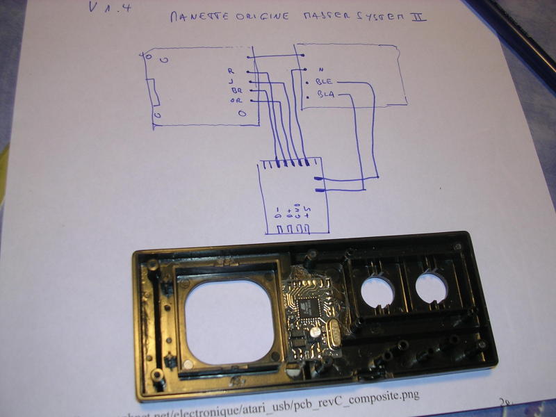
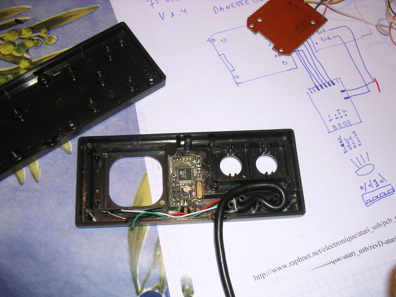
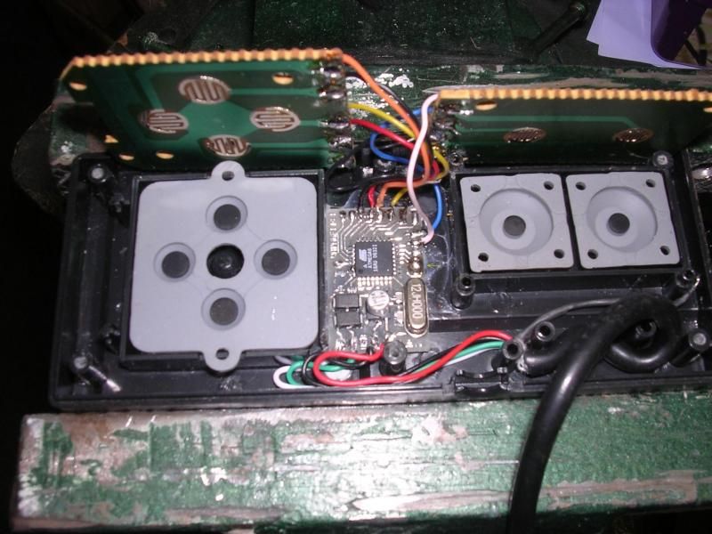
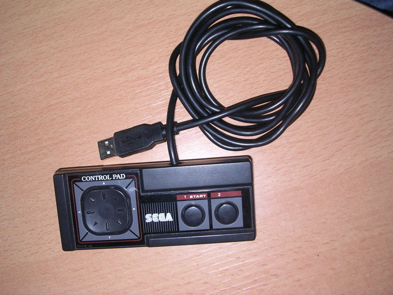
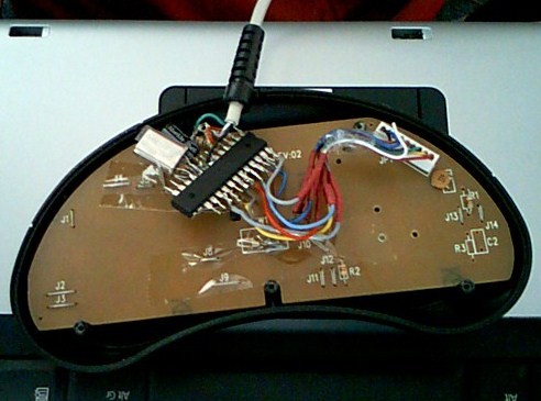
Someone from France sent me those pictures which are an excellent example of how one can mount the circuit inside a Sega Master System controller:
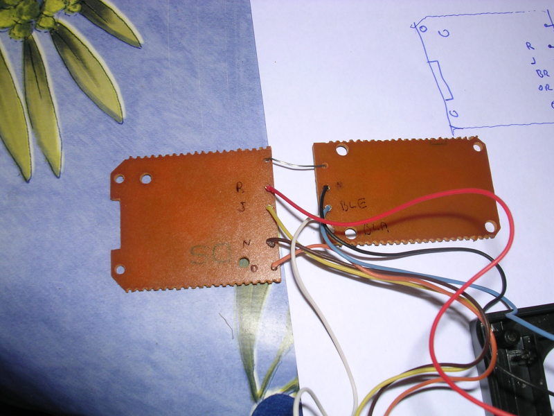
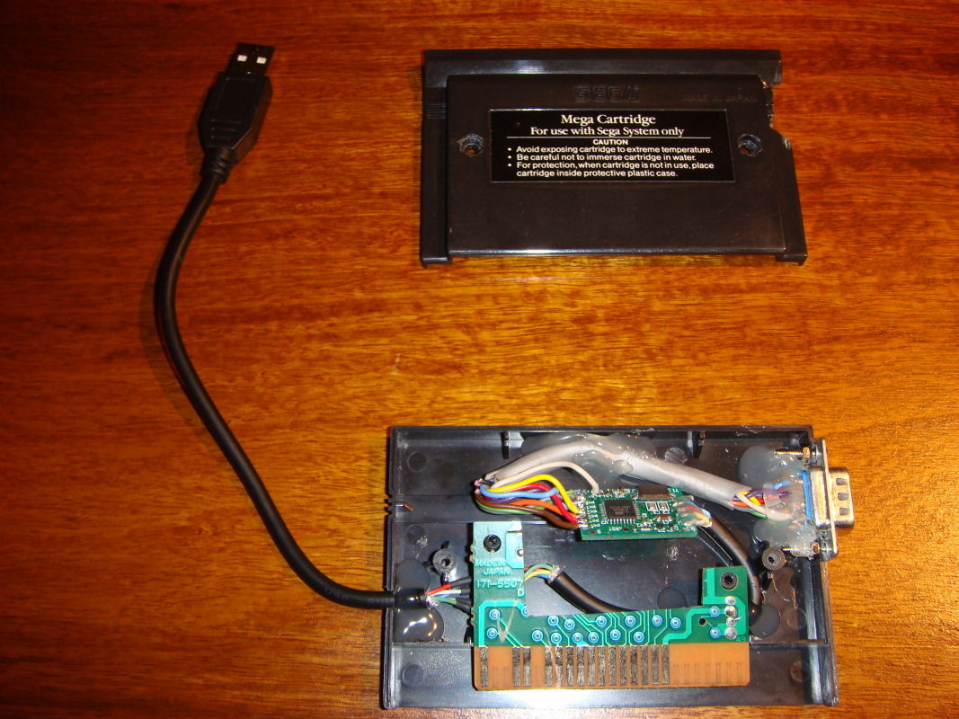
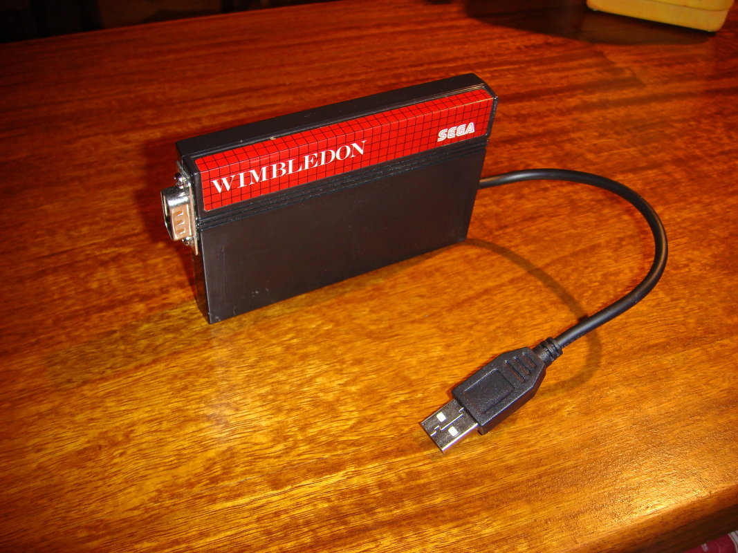
Laurent Quesnel installed the circuit inside an SMS game cartridge case:
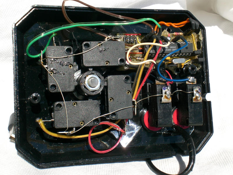
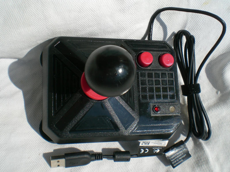
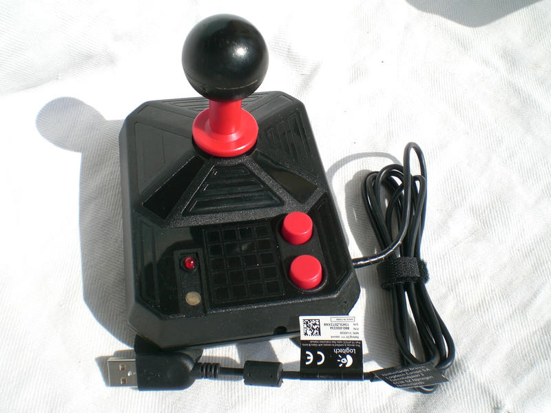
JP from the Netherlands built an USB Genesis controller:

Disclaimer
I cannot be held responsible for any damages that could occur to you or your equipment while following the procedures present on this page. Also, I GIVE ABSOLUTELY NO WARRANTY on the correctness and usability of the informations on this page. Please note, however, that the procedures above have worked in my case without any damages or problems.Now you cannot say that I did not warn you :)