Building an isolation transformer (and other related tools)
Insulation transformer
An isolation transformer is usually designed so that it has the same voltage at the input and output. (if we ignore losses)
          --) || (--
            ( || )
115 Volts   ) || (   115 Volts
            ( || )
          --) || (--
You can buy one in many electronic stores, but
if you want to save some money, you can build
one using two identical transformers.
         +--) ||                  || (--+
            ( || (--------------) || )
115 Volts   ) || )   35 volts   ( || (    * 115 Volts (see note below)
            ( || (--------------) || )
         +--) ||                  || (--+
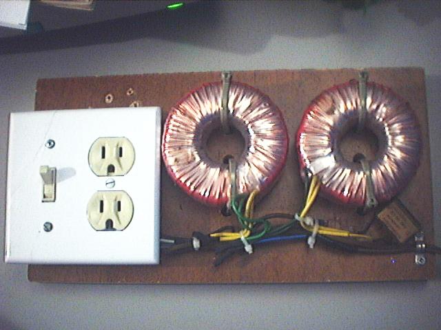
This is how I built mine. I used 2 transformers which
were not too expensive. I have included a switch, which
is very useful.Important note:
A reader kindly pointed out that I will never have 115 volt at the output due to transformer losses. Of course he is correct. However, this is not necessarily a problem.
The losses will be proportional to the load presented to the circuit. The higher the load, the higher the losses. In practice, here's how my setup, with those specific transformers performs:
| Input voltage | Output voltage | Load | losses(%) |
|---|---|---|---|
| 119 | 119 | None | 0% (Certainly not null, but very small) |
| 119 | 117 | 11W Incandescent light bulb | 1.5% |
| 119 | 114 | 25W Incandescent light bulb | 4.2% |
| 119 | 108 | 60W Incandescent light bulb | 9.2% |
Related tools
I will now introduce you to other tools I often use in conjonction with the isolation transformer.

|
On the picture on the left, you can see a Variac. A Variac
is in fact an autotransformer with a variable output.
Here is the schematic of a variac:
     COM -----) ||      The output voltage rages from 0 to IN.
              ( ||
              ) ||
      OUT  -->) ||
              ) ||
              ( ||
      IN -----) ||
This is very useful to obtain any ac voltage instantly, instead of looking
for a specific transformer. It can also be used to test power supplies,
when you want to see how they react to voltage variations.
|

|
Sometimes, a voltage higher than the mains voltage is needed. I use a auxilary transformer designed to step 347volts down to 115 volts. I just use the secondary as if it was the primary, and I obtain a 347 volts output. In combination with my variac, It can output any voltage between 0 and 347 volts. |

|
For safety in case of a short circuit, you can limit the
current by powering the circuit in series with a bigger load. I
use light bulbs, ranging from 10W to 150W, depending on the
expected load. In some situation, I have used a 1500W toaster oven. I learned this trick by reading the sci.electronic.repair faq. Here is the exact page. On the picture, you can see what I use to power a devices in series with a load. The switch on the left is the master switch, the switch on the right selects between a series output or direct output. The left part of the plug is the output, and the right part is for using another device as load. The light bulb is in parallel with the left part of the plug. |
Disclaimer
I cannot be held responsible for any damages that could occur to you or your equipment while following the procedures present on this page. Also, I GIVE ABSOLUTELY NO WARRANTY on the correctness and usability of the informations on this page. Please note, however, that the procedures above have worked in my case without any damages or problems.Now you cannot say that I did not warn you :)