CGA to VGA converter using an FPGA
The Tandy 1000 EX video outputs
The Tandy 1000 EX personal computer has two video outputs: NTSC composite video (For a TV monitor) and a CGA (Color Graphics Adapter) video output. More precisely, the Tandy 1000 video circuit is in fact of the TGA type, but electrically it is equivalent to CGA.Here are a few examples of images obtained through the NTSC output:

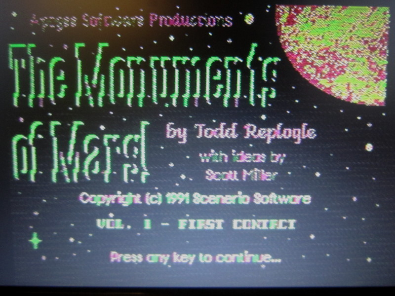
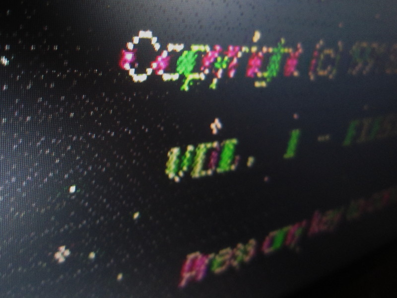

The NTSC image quality is way inferior to what can be obtained using CGA, but unfortunately I don't own a CGA display. On the other hand, as I have a surplus of VGA monitors, I became interested in finding a way to build a CGA to VGA converted.
CGA vs. VGA
CGA:
- Vertical refresh: 60Hz (Fixed)
- Horizontal refresh: 15.75 kHz (Fixed)
- 4-bit digital video output (Red, Green, Blue and intensity)
- DB9 Connector
VGA:
- Vertical refresh: 60Hz (Variable)
- Horizontal refresh: 31.46875 kHz (Variable)
- 3 Channel analog video (Red, Green, Blue)
- HD15 connector
Standard VGA monitors do not accept video with an horizontal refresh rate as low as 15 kHz. This means one cannot just build a simple adapter that just forwards the hsync/vsync directly and use a simple resistor based circuit to set the analog output voltages based on the digital CGA signal.
However, the VGA horizontal refresh frequency is approximately twice the CGA frequency. The VGA image has therefore about twice as many scanlines. By repeating each CGA scanline twice (and twice as fast) it is possible to kill two birds with one stone. First, obtaining a vertically compressed image occupying only half the screen is avoided, but the horizontal refresh frequency becomes high enough to be accepted by the VGA monitor.
This technique is known under the name "scan doubler".
The setup
This CGA to VGA project was the perfect excuse to buy an FPGA development kit (Altera DE1 from TerasIC) and plunge into the fascinating world of programmable logic.The kit routes several FPGA logic input/output pins to a convenient IDE-like 40 pin connector. It is however 3.3 volt logic and CGA video is TTL (5 volt) logic. In order to make sure the FPGA does not get damaged by this high voltage, I used a simple voltage voltage divider, like this:
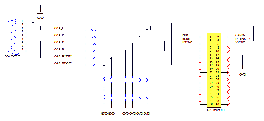
All resistors have equal values. I used 220Ω resistors, but I think this is a bit low since it results in an input impedence of only 660Ω while according to what I learned later, a real CGA display would have an input impedence of 4.7kΩ... If I were to redo this project, I would use 1.5kΩ resistors instead.
Here are a few pictures of the setup:

The DE1 kit

The kit and the voltage divider

A closer view on the voltage divider
Development
Here are a few pictures of the images I obtained in the beginning when I was just tinkering by modifying one of the examples that came with the kit to display data from a memory block fed by data from the CGA input. This approach was a dead end and I had to rewrite everything later, but at least I was able to confirm that all the signals were getting through.
No sync. at all

Horizontal sync only
The DE1 development kit has external memories I could have used, but to keep things simple I wanted to do everything in the FPGA. Unfortunately, this meant it was not possible to store a complete color CGA frame in memory. I therefore had to take a line by line approach.
So there are two buffers used in turn. While one scanline from CGA is being written to one of the buffers, the other buffer is being replayed twice as fast towards the VGA output. Each sample stored into memory comprises the 4 CGA color bits and the HSYNC/VSYNC signals as well. This means that I don't even need to generate new HSYNC/VSYNC signals as they are also simply replayed and sent as-is to the VGA monitor. But because of this, the VGA output is probably far from standard.

Too much jitter
I was tempted more than once to modify my Tandy 1000 computer to extract the pixel clock (through a BNC connector I would add at the back) but I resisted and persevered to finally obtain a stable picture!
However, it is only stable on a CRT. By looking very very closely, we can still see a bit of jitter, but it is within what I consider quite acceptable.

Problems on a LCD
All in all, I'm satisfied with my results for now as I'm using a CRT VGA display. But I will probably come back to this project later as I'm already thinking of improvements (rewrites).

Color glitches

A LCD monitor refusing the signal
Colors
One of the final touch was implementing correct colors. In order to quickly see color, I had initially written code that did the RGBI to RGB conversion using a simple naive approach:assign oR = {iIBGR[3],{7{iIBGR[0]}}};
assign oG = {iIBGR[3],{7{iIBGR[1]}}};
assign oB = {iIBGR[3],{7{iIBGR[2]}}};Wikipedia taught me that this is wrong. First of all, there is a spcial exception for yellow (to get a nice brown instead of a sickly dark yellow). But also, the RGB values to use are 0x00/0xAA when intensity is low, and 0x55/0xFF when high. Otherwise, there is not enough difference between colors 7 and 8 (Both are almost the same tone of gray).
So anyway, I rewrote the code to obtain the right colors:
always @(iIBGR)
begin
        if (iIBGR[3]) // High intensity/ light colors
        begin
                oR = iIBGR[0] ? 'hff : 'h55;
                oG = iIBGR[1] ? 'hff : 'h55;
                oB = iIBGR[2] ? 'hff : 'h55;
        end
        else
        begin
                if (iIBGR[2:0] == 3'b011)
                begin
                        oR = 'haa; oG = 'h55; oB = 'h00; // Brown is an exception (darker green)
                end
                else // Regular colors
                begin
                        oR = iIBGR[0] ? 'haa : 'h00;
                        oG = iIBGR[1] ? 'haa : 'h00;
                        oB = iIBGR[2] ? 'haa : 'h00;
                end
        end
end

Incorrect colors

Correct colors

For comparison: The NTSC horror!
I used the basic interpreter supplied with the Tandy 1000 boot disk to generate the color test screen above. Programming in basic brought back memories!
10 CLS
20 FOR I = 0 TO 15
22 FOR J = 0 TO 7
30 COLOR I,J
40 PRINT " ** ";
45 NEXT J
46 COLOR I,0
47 GOSUB 100
48 PRINT
50 NEXT I
60 COLOR 15,0
99 END
100 FOR T = 65 TO 90
101 PRINT CHR$(T);
102 NEXT T
103 RETURN
Scanlines effect
Omitting even lines on the VGA side creates a nice scanline effect.
Effect «scanlines»
The scanline effect is controller by SW0 on the DE1 development kit:
always @ (posedge VGA_CTRL_CLK)
begin
CGA_DATA_DOUBLESCAN <= (writebuf ? buf0_output : buf1_output) & ((vga_even & SW[0]) ? 6'h30 : 6'h3f);
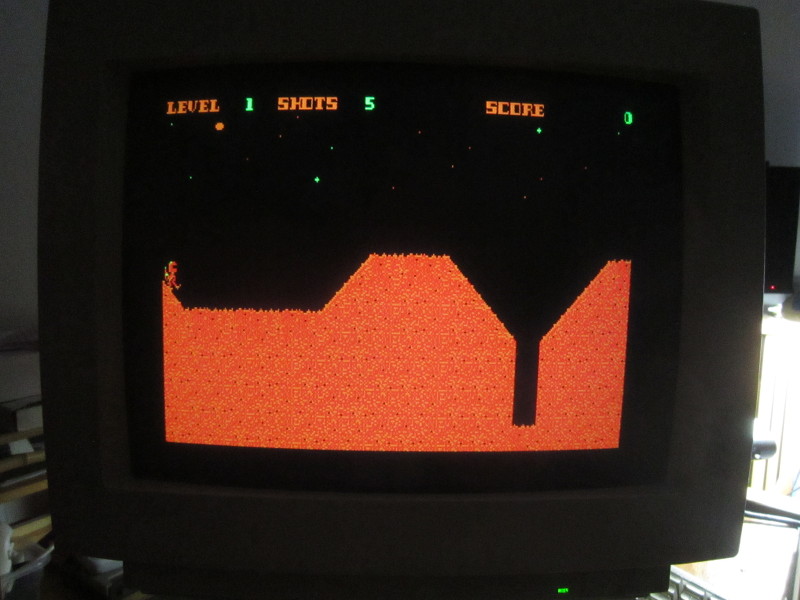
endThe result
Just compare the images here with those at the top of this article and you will come to the inevitable conclusion that the difference in quality is stupefying. In fact, the game looks exactly like it does when it runs on a PC with a VGA card. In fact, I think it's a bit too pure. I like it better with the scanlines effect enabled.
MS-DOS 2.11. Old.

Monuments of mars
Monuments of mars
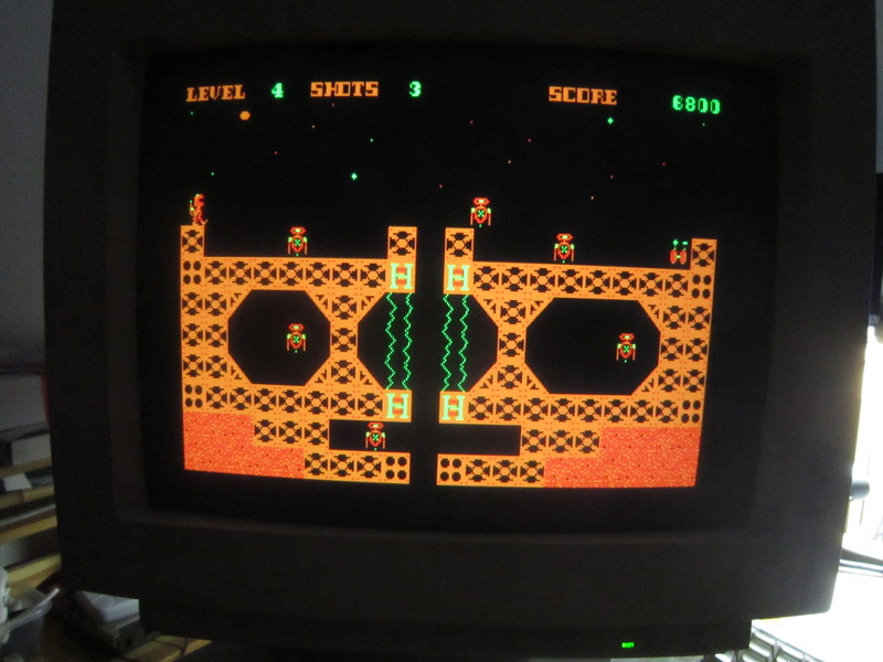
Monuments of mars
Source code
Warning: The source code is provided as-is without any warranty whatsoever. The quality of the code is without a doubt rather low, quite likely full of beginner's mistakes or unsound verilog programming practices and the comments are misleading. My excuse: It's my first FPGA project.| Version v1.0 November 22, 2015 (Sunday) |
|---|
| The first version (Line by line Scan doubler approach) without external memory. |
| File(s): cga2vga_scandoubler1.tar.gz (22 KB) |
References
| # | Description | Adresse |
|---|---|---|
| 1 | Lecture Notes | Complex Digital Systems | Electrical Engineering and Computer Science | MIT OpenCourseWare | http://ocw.mit.edu/courses/electrical-engineering-and-computer-science/6-884-complex-digital-systems-spring-2005/lecture-notes/ |
| 2 | Les exemples du CD fourni avec le kit Altera DE1 de terasIC | http://www.terasic.com.tw/cgi-bin/page/archive.pl?No=83 |
| 3 | Wikipedia: Color Graphics Adapter | https://en.wikipedia.org/wiki/Color_Graphics_Adapter |
Disclaimer
I cannot be held responsible for any damages that could occur to you or your equipment while following the procedures present on this page. Also, I GIVE ABSOLUTELY NO WARRANTY on the correctness and usability of the informations on this page. Please note, however, that the procedures above have worked in my case without any damages or problems.Now you cannot say that I did not warn you :)