Homebuilt anemometer
Introduction
 I wanted to build a measuring instrument which must be placed outside, exposed to the
natural elements. Some of my goals in doing this was to see how it would resist our
very cold canadian winter (sometimes -40 Celcius/Fahrenheit, not including
with wind, and yes, it did resist) and to learn from my
mistakes if something goes wrong.
I wanted to build a measuring instrument which must be placed outside, exposed to the
natural elements. Some of my goals in doing this was to see how it would resist our
very cold canadian winter (sometimes -40 Celcius/Fahrenheit, not including
with wind, and yes, it did resist) and to learn from my
mistakes if something goes wrong.I chose to build a cup anemometer ( link to wikipedia's anemometer entry ). This instrument has some electronics to keep track of the rotation speed and these components must be protected from water (Otherwise, oxydation would cause problems). Also, the mecanical parts must be able to resist strong winds, and cold temperatures. Moreover, the rotating part must offer the least resistance possible in order to be able to measure light winds.
To add a little more challenge to this project and make it less expensive, I decided to try to build
the anemometer using parts I already have, if possible. Here is a small list of parts:
|
 5 minutes average, image updated hourly. Click image for weekly, monthly and weekly graphs. Anemometer is located in St-Hubert, Quebec, Canada. |
Construction
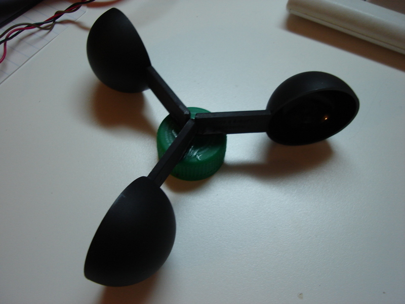 Here are the 3 cups the wind will set in motion. I used plastic coffee spoons from
the "one dollar" store. They cost me 1$ (CAN) each. It's the only thing I bought
for this project.
Here are the 3 cups the wind will set in motion. I used plastic coffee spoons from
the "one dollar" store. They cost me 1$ (CAN) each. It's the only thing I bought
for this project.I removed a part of the spoons handles and glued them to the coke cap, making sure there was a 120 degrees angle between each of them. I used crazy glue and hot glue. (Plastic + glue = easy to break? I'll see this winter...)
 The black thing on the picture is the component which allows an easy rotation. It's
a pinch roller salvaged from an old vhs VCR. It rolls really smoothly. When I spin
it with my fingers, it runs for 30 seconds or so.
The black thing on the picture is the component which allows an easy rotation. It's
a pinch roller salvaged from an old vhs VCR. It rolls really smoothly. When I spin
it with my fingers, it runs for 30 seconds or so.The 'U' shaped piece is the slotted infra-red sensor. One side of it is the infra-red emitter, the other side is a detector. After taking this picture, I glued a small tie-wrap plastic piece to the pinch roller so it blocks the infra-red beam once per turn.
Everything is mounted on the aluminium stick.
 The coke cap which holds the cups is glued on a spray paint cap. The cap is glued
to the pinch roller. The spray paint cap purpose is to protect what's under it from
snow and rain. There is still a small chance of water infiltration in the case of ascending
winds, but I decided to ignore this and hope for the best (tm).
The coke cap which holds the cups is glued on a spray paint cap. The cap is glued
to the pinch roller. The spray paint cap purpose is to protect what's under it from
snow and rain. There is still a small chance of water infiltration in the case of ascending
winds, but I decided to ignore this and hope for the best (tm).
 I used a triple contact terminal block as conector. The two first contacts are for 12 volts
DC power and the third one is the output. The signal stays at 12 volts except when the infra-red
beam is cut.
I used a triple contact terminal block as conector. The two first contacts are for 12 volts
DC power and the third one is the output. The signal stays at 12 volts except when the infra-red
beam is cut.
I wanted a strong output signal to prevent having capacitance and resistance problems due to the wire length so I built this simple circuit. It is sealed inside hot glue. Here is the schematic:
                     1k
     +--------------/\/\/-------+--------> 12 Volts
     |               1k         |
     |      c +-----/\/\/--+   e|
    \ / ->  |/             |  |/
    --- ->  |              +--|   2n3906 (PNP)
     |      |\v              b|\c
     |      e |                 +--------> Out
     |        |
     +--------+--------------------------> Ground
     Slotted IR
     sensor.
Installation
I installed the anemometer at the top of a pole that was previously used for an antenna. It's a little too close to the house and trees which are most likely modifying the wind trajectory and speed. Even if the location is not optimal, it works.

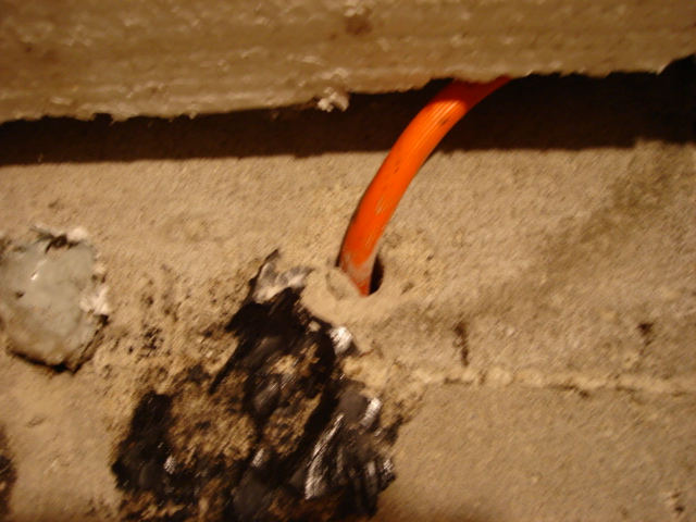
I used an old exterior power cord which enters the basement via a hole I've drilled in the concrete:
Spring 2006: The anemometer has survived winter! And it still works perfectly.

Controller
 Building and installing the anemometer is not all. We must be able to measure the speed and
send it to a computer if we want to do more than look at a blinking led. To build the controller,
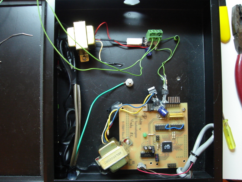
I recycled an old prototype board I had made at work in 2003.
Building and installing the anemometer is not all. We must be able to measure the speed and
send it to a computer if we want to do more than look at a blinking led. To build the controller,
I recycled an old prototype board I had made at work in 2003.There are 2 transformers because I wanted the outdoor equipment to be electrically isolated from the equipment indoor. The upper left transformer powers the outdoor stuff. There is a big resistor that is there to heat in case there is a short circuit outside. There is also a diode bridge and a capacitor to make DC from AC.
The signal from the anemometer makes an opto-coupler's internal led blink. The microcontroller monitors the signal coming from the opto-isolator to measure the rotation speed. It communicates with a computer over an rs232 link.
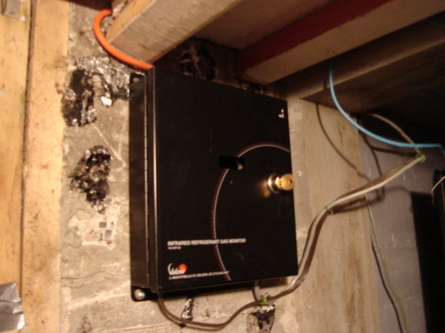
Here are a few pictures of the controller screwed directly into the basement concrete wall. (I like that, it's very solid)

Software
Microcontroller:The microcontroller I used is an Atmel ATmega128 (Yes, it's overkill). It is programmed to calculate the time each revolution takes. Each time a revolution is completed, the time it took, in milliseconds, is transmitted to a computer via an rs232 link at 9600 bauds using the following syntax:
delta: xxxx\nWhen nothing is happening (no revolutions for more than 10 seconds), a message is sent to the computer so it can log that the wind has stopped:
status: stopped\nHere is a file containing the source code: (compiles with gcc and avr-libc)
windmon_avr.tar.gz
And if you want to look at the code right here:
main.c usart.c usart.h
Logger:
On the computer, at each second, a program records the last 5 minutes average and the last 5 minutes top speed.
Here is the source code of this program: windmonitor.c
And some related scripts:
Configures the serial port and starts windmon-run in background: windmon-init
Starts windmon with a specified log file and redirects the serial port into windmon stdin: windmon-run
Remote retrieval of the data:
I use snmp to remotely retreive the most recent values. Here are the lines I added to my snmpd.conf file for this:
exec windspeed /usr/local/bin/windmon-getlastaverage
exec windspeedmax /usr/local/bin/windmon-getlastmax
And here are the scripts:
Returns the last 5 minutes average speed: windmon-getlastaverage
Returns the last 5 minutes top speed: windmon-getlastmax
Graphing the data:
I use mrtg to generate the graphs from the snmp source. Here is the relevant par from my mrtg config file:
Target[wind]: 1.3.6.1.4.1.2021.8.1.101.1&1.3.6.1.4.1.2021.8.1.101.1:public@cola
SetEnv[wind]: MRTG_INT_IP="xxxxxxxxxxxxx" MRTG_INT_DESCR="ping"
Title[wind]: Wind speed
MaxBytes[wind]: 2000
AbsMax[wind]: 2000
Options[wind]: gauge
YLegend[wind]: Revolution Per Minute
ShortLegend[wind]: rpm
PageTop[wind]: <H1>Wind speed</H1>
 <TABLE>
   <TR><TD>System:</TD>     <TD>ND</TD></TR>
   <TR><TD>Maintainer:</TD> <TD>Raphael Assenat (raph@raphnet.net)</TD></TR>
   <TR><TD>Description:</TD><TD>Wind speed in rpm </TD></TR>
   <TR><TD>Max Speed:</TD>  <TD>2000 rpm</TD></TR>
 </TABLE>
The results:
5 minutes average, image updated hourly. Click image for weekly, monthly and weekly graphs. Anemometer is located in St-Hubert, Quebec, Canada.
Conclusions
I have not taken the time to calibrate my anemometer before installing it, so I cannot map it's rotation speed to wind speed. However, I'm able to see how the wind fluctuates.In the future, I will add more components to my weather monitoring system to gather more data such as wind direction, humidity, temperatue, lightning detection, rain detection, luminosity, air pressure...
Once I will have installed my other sensors, I will try to find relations between the wind speed and other measures. (eg: how does fast temperature changes influence the wind's speed?)
Meanwhile, I can't wait to see how my homebuilt anemometer will fare this winter.