PCjr cartridge
Intro: The IBM PCjr?

| PC | PCjr | |
|---|---|---|
| Video | 320x200, 4 colors | 320x200, 16 colors |
| Sound | One channel, square wave, fixed volume. | 3 Channels + noise, programmable volume |
| Joystick port | As an option (expansion card) | Two built-in ports |
The video circuit supports a 320x200 graphics mode where simultaneous use of 16 colors is possible. (vs. only 4 on PC/CGA), and and the audio side of things, the PSG SN76496 chip, with its 3 channles (square wave with programmable volume) + noise channel is much more capable than the PC speaker (fixed-volume single square wave channel).
Despite the critics and the commercial failure of the PCjr, for someone like me who like programming games for old PCs (such as RATillery) the PCjr has a very interesting unique element: Cartridge slots! (just like game consoles and many non-PC systems such as the Commodore 64!)

Above: The PCjr front side with its two cartridge slots.
Project overview
So I thought it would be fun to make my own cartridges for the PCjr. I'm not the first to accomplish this, for instance here is a PCjr cartridge project I found on hackaday.io. Regardless, I wanted to make my own version using a single 64k ROM instead of two 32k ROMs. And I also wanted to make one because if I ever try selling a game on cartridge, I'd rather use my own design instead of profiting from someone's else work...In a nutshell, here's what I created:
- A Circuit board able to hold a single 64k or 32k chip
- A 3D-printable enclosure for a not-so-bad end result without using original cartridges as donors
- A tool to convert self-contained .COM and .EXE DOS executables to cartridge format
Schematic and PCB (v1)
The chip select signals driven by the PCjr correspond to a series of consecutive 32k memory ranges:
I decided to use CS4 and CS5. If I had used two 32k ROM chips, it would have been a simple matter of wiring each chip select to a seingle chip. But in this case, as I used a single 64k chip, I had to add a 74LS08 (AND gate) so that when either of the chip select signals would fall low, the ROM output would be enabled.
This probably begs the question: What's the point of using a single ROM if you still need to install two chips in the cartridge!? The answer: Les expensive and less pins to solder (so faster). The 64k ROM only costs 12% more than the 32k model in the same family (AT27C512R vs. AT27C256R), there is only one ROM to program (less manufacturing steps) and a lower number of pins to solder (the 74als08 hcip only has 14 pins, whereas a 32K ROM has 28...).
Now, here is the schematic:

And now here are a few pictures of the printed circuit board:

Component side

Solder side

Bevel
I installed an IC socket on the first unit for easy ROM replacement and testing. This uses more vertical space, but it still fits:

Test

Test
Schematic and PCB (v3)
After some time, I wanted to try new things, such as using 32k EPROMs (which should normally have 5 volt applied to pin 1) and using CS6 and CS7 to test a modified BIOS. But my first design was not really meant for this...So I made a new design! This one can be configured to use different Chip Selects through solder blobs. I chose not to use jumpers because in production (when assembling many cartridges) it is faster. Not to mention a bit cheaper too.
The new design also has proper 32K ROM support. Here is the schematic:

Here are a few pictures of the new PCB:

Component side

Solder side

Configuration

Example replacing the BIOS
I ordered a moderately large quantity, so I am also selling those below:

Oh, and in case you were wondering what happened to version 2, yes, it exists. It is almost identical to version 3, but I made a catastrophic mistake when routing the PCB and do not have anything useful to show.
Enclosure
My PCB is designed to match the dimensions of the original IBM circuit board I used as a model, so installing it in original cartridge shells is possible. However, destroying original IBM cartridges to install a new board feels wrong, so I decided to make my own with a 3D printer.I tried designing and printing a cartridge with snap hooks similar to those of the IBM cartridges. On my monitor it looked fine, but once printed, the fate of the hooks was clear: Break!

Hooks that failed
I must have tried printing 4 or 5 versions, adjusting the hook geometry each time, but in the end I have up the idea... I decided I would just use screws. But I used some kind of jigsaw pattern in the front to save two screws there.

Cover

Base
The .STL files for 3D printing are here: jrcartv7.zip
Here are a few pictures of the final version. The circuit board inside is not mine, it's the board from a BASIC cartridge.


Converting DOS executables
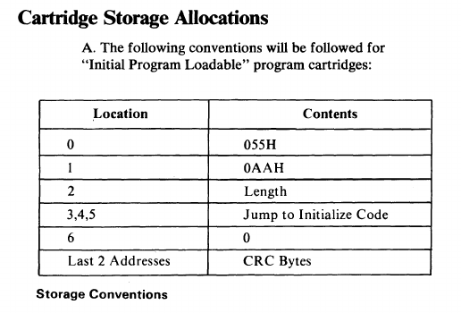
A while ago I developed a tool called Booterify which is able to convert standalone .COM and .EXE executables to bootable disk image, so all the hard work was already done. I just had to replace the code which reads sectors from the floppy disk by a simple memory copy routine (copies from ROM to RAM).But that's only the first step. Unless some conditions are met, the PCjr will not transfer control to the program stored in the cartridge ROM. The requirements are documented in the PCjr technical manual:
In other words:
- The two first bytes must be 0x55 and 0xAA.
- The third byte indicates a size, given in 512 byte blocks.
- The code (typically a JMP instruction) is at the 4th byte.
- The last two bytes are a CRC 16 (same polynomial as used for Xmodem).
First, Booterify's job:
- The loader (pcjrloader.asm) is compiled by nasm.
- Booterify loads the compiled loader (pcjrloader.bin) and the executable (for instance, GAME.COM)
- Booterify patches the loader with informations about the executable (Initial segment values, initial instruction pointer) and also patches the executable if necessary (i.e. EXE relocations).
- Booterify outputs a file containing the patched loader followed by the core of the executable.
EXECUTABLE=GAME.COM
LOAD_SEGMENT=0x0051
./booterify -f 0 -s $LOAD_SEGMENT -pcjrloader.bin $EXECUTABLE tmp1.bin- Adjust the size so it's a multiple of 512.
- Write the correct size in the ROM header (3rd byte) using the -s option.
- Compute the CRC and write it at the end with the -p option.
./jrromchk -s -p -o rom.bin tmp1.binIf you are doing development, testing inside an emulator first can save you a lot of time, especially if you use UV-erasable EPROMs which require several minutes to erase.
The SVN version of DOSBox supports the pcjr machine type and can load PCjr .JRC roms using the BOOT command. This is extremely useful! That's why jrromchk offers the option of generating a .JRC file using the -j option:
./jrromchk tmp1.bin -s -p -o rom.jrc -jMaking an Alley Cat cartridge!
The game Alley Cat (is an introduction necessary?) makes use of the additional sound and video capabilities of the PCjr. 3-channel sound is only used at the title screen. For graphics however, the game makes good use of a 4-color mode where individual colors can be selected, rather that being retrained to the much loved/hated CGA colors. This means that the cheese is.. well it's yellow at last!
CGA Version (This cheese is NOT appetizing)

PCjr Version
Alley Cat was originally a PC Booter, that is a game which does not (typically) use DOS and starts directly from its floppy. The original Alley Cat floppy without doubt works fine on the PCjr... But having a cartridge version of this excellent classic game would be very exciting, wouldn't it!? You want one, yes? Of course you do.
Step 1 : Obtaining the game in executable format
There are a few DOS conversions of Alley Cat floating around (for instance, CAT.EXE) on the net, but some are missing the PCjr-specific code, others had their title screen vandalised by the individual who did the conversion to DOS format (.COM or .EXE) from the original PC Booter disk. My recommendation is therefore to work from the original disk, or otherwise from a disk image (for instance, ALLEYCAT.IMG...)
Some time in 2015, the game got patched to enable enhanced sound and graphics on the Tandy 1000 computer series (Those are clones/successors to the PCjr), and the version posted by NewRisingSun in the vogons.org forum thread dated December 13, 2015 contains the MAKEDOSV.COM tool (Make Dos Version?) which will read the original floppy and create ALLEYCAT.EXE. Just insert your disk, type MAKEDOSV and a few moments later you'll have a parfectly working and intact ALLEYCAT.EXE in the current directory.
If you only or already have a floppy image, you can also use MAKEDOSV and DOSBox to create an executable. Simply place ALLEYCAT.IMG and MAKEDOSV.COM in a directory of your choice, start DOSbox there and type:

For reference, here are the MD5 of the files involved here:
	9c003a2dbb48704a47b499d42ad49e55  ALLEYCAT.EXE
	5bbf1bd48e652c66cf704c2e1f80e9a7  ALLEYCAT.IMG
	3ceea0a7d6060f6d8d340c649770fe66  MAKEDOSV.COM
Étape 2 : Convert the executable to a ROM
./booterify -s 0x0051 -f 0 pcjrloader.bin ALLEYCAT.EXE tmpcat.bin
./jrromchk -s -p -o ALLEYCAT.ROM tmpcat.bin

# Optional: A .JRC version for testing in DOSBox
./jrromchk -s -p -o ALLEYCAT.JRC -j tmpcat.bin
Step 3 : Program your ROM, put it in the cartridge...
Now you need to program a ROM with the contents of the ALLEYCAT.ROM file created above. How this is done depends on your programming equipment and is outside the scope of this article.
Install or solder the programmed chip on the cartridge circuit, insert the cartridge in the PCjr, turn it on.... And here you go!

Now, why not a small video where you can listen to the 3 channel version of the theme song?
References
| # | Description | Link |
|---|---|---|
| 1 | IBM PCjr Technical Reference Manual For the cartridge pinout and BIOS startup requirements. |
https://archive.org/details/IbmPcjrTechnicalReference |
| 2 | Disassembled BIOS from 8088 machines PCjr code listing, easier to use than what's printed in scanned IBM manuals. I used this to learn a few things such as the type of CRC I had to use. |
https://github.com/ricardoquesada/bios-8088 |
| 3 | JRipCart (Tand-Em Project) Contains documentation about the .JRC PCjr cartridge ROM image format. (Included with JRipCart in CODE/JRCSPEC.TXT) |
http://www.oldskool.org/pc/tand-em/jripcart/ |
Disclaimer
I cannot be held responsible for any damages that could occur to you or your equipment while following the procedures present on this page. Also, I GIVE ABSOLUTELY NO WARRANTY on the correctness and usability of the informations on this page. Please note, however, that the procedures above have worked in my case without any damages or problems.Now you cannot say that I did not warn you :)