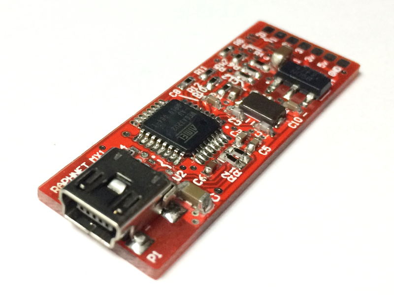
Multiuse PCB-X : A small multipurpose PCB with an USB micro-controller
Description
Besides the higher transfer rate, it is also possible to have the host (the PC) poll the adapter at closer intervals, which is a great way to reduce latency. Also, since the micro-controller does not handle low level USB communication in real-time anymore, some restrictions are lifted. For instance, disabling interrupts during time critical operations, a necessity difficult to work around in many situations, is no longer prohibited.
Specifications:
- Atmel atmega32u2 micro-controller clocked at 16MHz.
- Mini USB connector
- 8 input/output pads
- 3.3v, 5v and GND pads.
- LM1117-3.3 (800mA LDO) 3.3v regulator on-board
- Dimensions: 1.825" x 0.619" x 0.217" (46.36mm x 15.73mm x 5.5mm)
- Pre-programmed with Atmel DFU bootloader. Flash your own firmware through USB without special equipment!
- Compatible with Dean Camera's LUFA library.
Signals
The board has a mini-USB connector, so it is a simple matter of connecting a cable. For the remaining signals, solder PADs are available.| Signal | Side | Label |
|---|---|---|
| PD0 (INT0/AIN0) | Component side | 0 |
| PD1 (INT1/AIN1) | Component side | 2 |
| PD2 (INT2/AIN2/RXD1) | Component side | 1 |
| PD3 (INT3/TXD1) | Component side | 3 |
| PB1 (SCLK) | Solder side | SCK |
| PB2 (MOSI) | Solder side | MOSI |
| PB3 (MISO) | Solder side | MISO |
| PD7 (HWB) | Solder side | HWB |
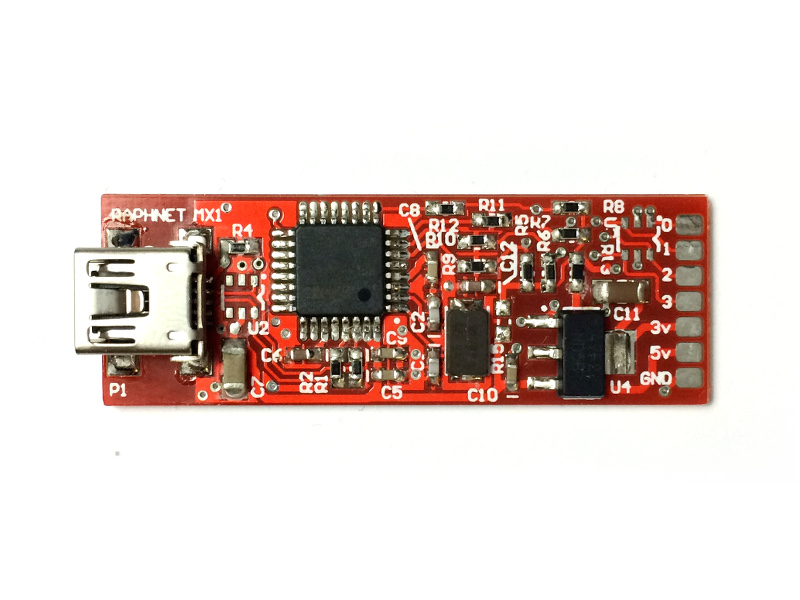
Component side
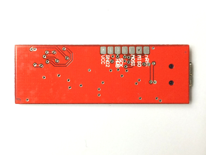
Solder side
Yes, the labels 2 and 1 are inverted.
Schematic
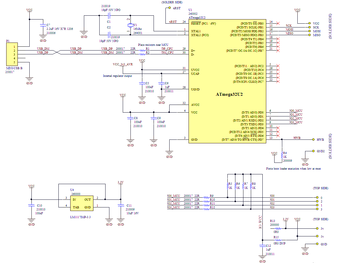
- The R5 to R8 pull up resistors can be configured to pull to 3.3v (default) or 5v (option). The voltage is selected by installing R15 instead of R13.
- The R9 to R12 series resistors help protect the MCU IO pins. Since a fairly low value of 22Ω is used, this does not cause problems.
- Components labelled "DNP" are not installed by default. (Note: DNP = Do Not Place)
Programming
Option 1 : DFU Bootloader
The Atmega32u2 micro-controller this design is based on is programmed with an USB DFU (Device Firmware Update) bootloader at the factory. This means it can be user-programmed with a PC utility without requiring an AVR programming dongle.To install a firmware however, one must first enter bootloader mode. There are a few ways:
- When the chip is new, just connecting the USB cable is enough. The bootloader does nothing when no firmware has been installed.
- If the chip has been programmed with a firmware:
- Send a command that makes the firmware jump in the bootloader.
- While keeping the HWB signal low by connecting it to GND, perform a reset using the RESET pad.
# Flashing a (new) firmware with dfu-programmer
$ dfu-programmer atmega32u2 erase                   # Step 1: Erase the current firmware
$ dfu-programmer atmega32u2 flash firmware.hex      # Step 2: Flash the new firmware
$ dfu-programmer atmega32u2 start                   # Step 3: Start the new firmware
Option 2 : AVR-ISP
This is the traditional approach to programing AVR micro-controllers using a programming dongle. Not necessary for this board, but sometimes it can be useful:- To install a different bootloader
- To use all the available flash memory (overwriting the bootloader)
- To change the fuse bytes
Development
LUFA
I recommend the use of LUFA (http://www.fourwalledcubicle.com/LUFA.php), an excellent USB framework. This project is very popular so there are tons of examples for a panoply of USB peripheral types. There is also a mailing list if you need help.Here is an example using LUFA: MouseShaker.tar.gz. This firmware, derived from the Demos/Devices/ClassDriver/Mouse example supplied with LUFA implements a mouse that continuously spins around. Almost useful as a screensaver inhibitor.
LUFA alternatives
The LUFA documentation mentions a few alternatives. I did not try any of them.Alternative USB AVR Stacks
DIY From scratch
If is of course possible to develop your own USB framework by reading the datasheets and using the micro-controller registers directly (This is what I did for my PPUSBComm project). A great way to learn about how everything works, and necessary if you want to own the rights to use it the way you please. But be ready to spend a lot of time on it.Projects
raphnet projects
| Projet | Description |
|---|---|
| Gamecube/N64 controller to USB adapter | The third generation of my N64/Gamecube to USB adapter uses this design. |
| PPUSBCOMM | PPUSBComm is a tool to copy files from a Linux system with USB ports to a system running DOS with a parallel port. |
User projects
If you built something using my circuit, I would be delighted to list and link to it here. Please let me know!FAQ
If you have questions, please don't hesitate to contact me.Meanwhile, here are a few entries I anticipate:
- Q: Where can I buy an assembled board?
- A: This PCB is sold pre-assembled with an USB cable and a piece of heat shrink tubing in my online store.
- Q: There are already abordable and similar boards (Eg: Teensy) on the market. Why did you design a new one?
- A: To get exactly and everything I needed:
- Dimensions and geometry that works well for building my joystick adapters (eg: To enclose the circuit in heat-shrink tumbing, it must have an elongated shape and it is preferable that the wires exit from the ends rather than the sides)
- To have an on-board 3.3v regulator able to supply power to several Gamecube and N64 controllers
- To have 3.3v pull-up resistors even though the micro-controller is supplied 5 volt
- To be able to build them in large quantities to obtain a beter (the cost) price. This translates to lower prices for my adapters.
Disclaimer
I cannot be held responsible for any damages that could occur to you or your equipment while following the procedures present on this page. Also, I GIVE ABSOLUTELY NO WARRANTY on the correctness and usability of the informations on this page. Please note, however, that the procedures above have worked in my case without any damages or problems.Now you cannot say that I did not warn you :)