Arcade style controller for Snes, NES and PC
Overview
 The feeling you get when playing a game using an arcade style controller differs
from the feeling of a gamepad or keyboard, and in my opinion is better for
many games.
The feeling you get when playing a game using an arcade style controller differs
from the feeling of a gamepad or keyboard, and in my opinion is better for
many games.I met someone who buys old arcade cabinets to repair them, and upgrade them with a PC running mame. He had some spare parts such as buttons and joysticks. I got the idea to use them to build an arcade style controller for my Snes, NES and PC.
Schematics
Since a snes gamepad is nothing more than a 16 bit wide parallel load shift register, I build my controller circuit using 2 74ls165. An inverter was needed to change the polarity of the latch (74ls165 latch input is active low, snes uses active high..). I first used a 74ls04, but replaced it by a transistor/2 resistors combination later.It is necessary to use 74ls165. 74hc165 wont work because they dont appreciate the clock being high when the latch is low.
The shift in (ser) input of the second shift register is kept low to make sure the final state of QH (data) after the 16 clock pulses is low. If it is not low, some games wont detect the controller (eg: Donkey Kong).
I named the last 4 bits E1 to E4. On a regular snes gamepad, they are not used for buttons, they are kept high. They are used(or one of their use is) to identify the type of equipment connected to the port. In the case of a mouse for instance, E4 is low instead of high. Direct Pad Pro, Zsnes dos and Linux only sends 12 clock pulse, so they merely ignore those bits. But many games on a real SNES do look at those bits and do not detect a controller if they are not high.
The pull-up resistors in the drawing below do not have a value. Anything from 1k to 22k should work.
A note about PAL SNESes: A user reported that it would not work until he installed an 1.2kohm pull-up on the clock line. (3k would not work). In his final build he lowered the value down to 467ohm. The reason why this was necessary is not clear currently...


For a best reading here's the pdf version of this schematic.
Here is how you can build an inverter with a transistor. Useful if you dont have 7404s around, if you think using only 1 inverter out of 6 is ridiculous or maybe to save money.
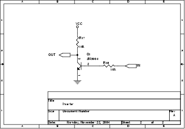
For a best reading here's the pdf version of this schematic.
To power the circuit from a parallel port, it is possible to use 5 diodes to collect some current from output pins. There can be problems with some ports as the voltage can drop because of the load, and the voltage drop of the diodes. The 74ls165 needs 5 volts to work, so parallel ports giving only 3.3 or 3.5 volts (like it is common on new PCs) will be no good for powering this circuit. If you have voltage problems, you will need to find another source of power. Using the gameport is a good way to get 5 volts (DB15F, use pins 1 (+5v) and 4(Gnd)). Measure first, some gameports also work at 3.3 volts... Also, the PS/2 keyboard/mouse ports are good source for 5 volts you can trust.
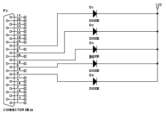
For a best reading here's the pdf version of this schematic.
In order to be able to connect this circuit to a Snes or NES, I built a simple cable. I used the cables from original Snes and NES controllers. You may choose to build only the NES or Snes part of the cable:


Pictures
 First of all, I tested the circuit to make sur it actually worked.
 Here is what the signals entering the 74ls165 look like. The higher signal on the
picture is the clock and the lower signal is the latch.
Here is what the signals entering the 74ls165 look like. The higher signal on the
picture is the clock and the lower signal is the latch.
 Here's more signals. The higher signal on the picture is the clock and the lower signal is the data. In
this picture, the START button is pressed.
Here's more signals. The higher signal on the picture is the clock and the lower signal is the data. In
this picture, the START button is pressed.
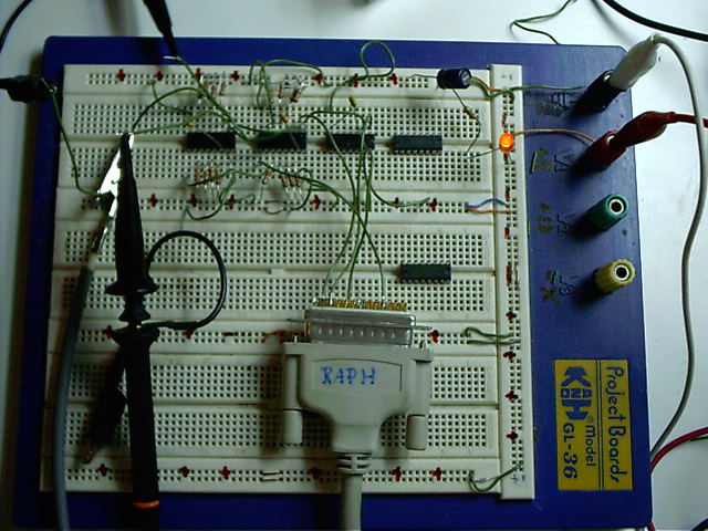
 The circuit completely assembled. The pull-up resistors used for each button are surface mount resistors
soldered under the circuit board.
The circuit completely assembled. The pull-up resistors used for each button are surface mount resistors
soldered under the circuit board.
 To decide what was the optimal button positions for my hand, I did some tests using
cardboard. Once I felt it was acceptable, I drilled the holes in a wood board.
To decide what was the optimal button positions for my hand, I did some tests using
cardboard. Once I felt it was acceptable, I drilled the holes in a wood board.
 The buttons and joystic cabling. Quite simple. One common wire for all buttons (including joystick
direction buttons) which goes to the ground and one wire per button that connects to the terminal
block on the circuit.
The buttons and joystic cabling. Quite simple. One common wire for all buttons (including joystick
direction buttons) which goes to the ground and one wire per button that connects to the terminal
block on the circuit.
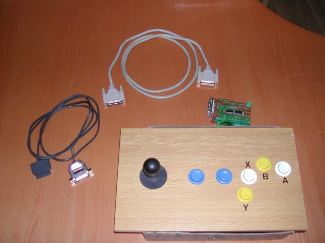 An overview of all the components(Button + Joystick panel, circuit, cables). I still
have to build a base to hold the panel. 2 buttons are missing (L and R) to have the equivalent
of an Snes controller. It think I will install them on the sides (good for playing pinball) and
maybe assing them to paddles (good for Mario Kart).
An overview of all the components(Button + Joystick panel, circuit, cables). I still
have to build a base to hold the panel. 2 buttons are missing (L and R) to have the equivalent
of an Snes controller. It think I will install them on the sides (good for playing pinball) and
maybe assing them to paddles (good for Mario Kart).Arcade buttons and joysticks can be bought from Wico.
Protocol
If you want to learn the communication protocol(an impressive word for simple shift registers) of an snes gamepad, I suggest you read this document: Super Nintendo Entertainment System: pinouts & protocolTo learn more about shift registers and how to use them in smart ways:
shift.txt
Software
To use this controller on a Snes, nothing more than a regular Snes game is needed. To use it on a PC, you just use the same software you would use for regular snes gamepads. Direct Pad Pro, PsxPad, Zsnes Dos, Linux...Please consult the software section of my page about Snes controllers on a PC for more details about where to download required software.
Disclaimer
I cannot be held responsible for any damages that could occur to you or your equipment while following the procedures present on this page. Also, I GIVE ABSOLUTELY NO WARRANTY on the correctness and usability of the informations on this page. Please note, however, that the procedures above have worked in my case without any damages or problems.Now you cannot say that I did not warn you :)